AlxUnderBase
Enlightened
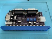
Sir ... i must crim the psu harness between Minigun and PSU and i don't know how to match the color to terminations and i don't know long must be the cables i must crimp. can you tell how to do it ?Looks great, well done.")
Need the money shot next, i.e. picture of it running.
 will be my first harness made by me
 ? i'm almost done