What's new
Which resistors correspond to r, g and b. There are 4: R1-R4. I assume one is for sync. Is R4 sync?
R1-R4 are 75 ohm (at least in advanced version). It's specified in the BOM pdf included in the zip file.
 
Try 0.4V for each pot if 0.45V is too bright.

I'm over compensating a little as my CRT is a Bang & Olufsen which has a tinted screen in front of the tube.

R4 is sync, R1 to R3 are RGB. You'll know which is which by turning the pots and seeing which colour changes.
 
Thank you. I modified R1-R3 to .45v and it’s a bit bright when used with OSSC and GScart. I’ll tweak them down a bit to fit my likings. I generally turn on scanlines as I’m old school.

Btw I was testing this with a cps2. Went to test mode to see the rgb grid.
 
Try 0.4V for each pot. :)

That should be spot on. I forgot that I run mine a little higher due to my TV needing a bit more brightness.
 
Making progress on the 3d printed case design. I built it to easily adjust to future layout changes. Also, there is some reinforcement in the case structure for the JAMMA connector and DB15 connectors so they are supported. Feels really sturdy in the hand. Attached with 4 x M3 screws and nuts. I'm using a 3mm light pipe for the power LED. Most of the switches are accessible, I omitted the B4 and LPF for now, but those can be added. I will publish it on Thingiverse once it is completed.

IMG_1839.jpg
IMG_1826.jpg
 

Attachments

  • IMG_1827.JPG
    IMG_1827.JPG
    172.5 KB · Views: 267
Got my 1.7 built and somewhat tested! Worked first try! Only thing is that the OSSC to my monitor is a little off on the horizontal position and I'm not super sure how to fix it. Also I'm pretty sure I got the LED backwards but can't really tell, as it doesn't come on. Please excuse the mess in the background.

rLXyiDK.jpg


CKOtcDU.jpg
 
Can anybody try to explain how the potentiometers work to adjust the input signal?

I've always been confused because I thought they are only adjusting (i.e. lowering) the RGB voltage. For example, if the Neo Geo RGB is 4v p-p then it must get reduced to 0.7v p-p for the OSSC, etc.

Am I correct in my understanding or is it more complicated than that?

I'm further confused because I thought the THS7374 can only accept a ~0.7v p-p input voltage? Therefore if the potentiometer is set to 0, then the full ~4v p-p is being sent to the amplifier?

Thanks for any clarification :)
 
RGB outputs from arcade PCB, at levels around 4Vp-p

Pots are wired as a voltage divider, which adjusts the input voltage to the THS7374. As the THS doubles the signal upon output, we're feeding it 1/4 of the voltage at input of what we desire upon output.

The THS can accept full level video signals, up to 1.46Vp-p.
 
Making progress on the 3d printed case design. I built it to easily adjust to future layout changes. Also, there is some reinforcement in the case structure for the JAMMA connector and DB15 connectors so they are supported. Feels really sturdy in the hand. Attached with 4 x M3 screws and nuts. I'm using a 3mm light pipe for the power LED. Most of the switches are accessible, I omitted the B4 and LPF for now, but those can be added. I will publish it on Thingiverse once it is completed.

IMG_1839.jpg
IMG_1826.jpg
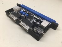
Put me down for one if you decide to make and sell these!
 
To tackle the Undamned encoders not fitting side by side, I've shifted the TEST and SERVICE switches to the centre of the DB15s.

My sense of symmetry dislikes this as before the DB15's were perfectly centered but oh well. :)
PCB_PCB-ADV-1.8_20190811170017.png
 
RGB outputs from arcade PCB, at levels around 4Vp-p

Pots are wired as a voltage divider, which adjusts the input voltage to the THS7374. As the THS doubles the signal upon output, we're feeding it 1/4 of the voltage at input of what we desire upon output.

The THS can accept full level video signals, up to 1.46Vp-p.
Is the voltage level still safe (under 1.46Vp-p?) if the potentiometers are off? (i.e. turned all the way to the left)

Also ... is the goal to get a specific voltage to the THS regardless of the arcade board? For example, is the goal to always send 0.7Vp-p into the THS for correct levels?

To tackle the Undamned encoders not fitting side by side, I've shifted the TEST and SERVICE switches to the centre of the DB15s.

My sense of symmetry dislikes this as before the DB15's were perfectly centered but oh well. :)
PCB_PCB-ADV-1.8_20190811170017.png
It definitely still looks awesome ... If anybody wants to split the cost of ordering some PCBs (after the new design is finalized), let me know.
 
Re the THS7374, there's a few considerations:

Input voltage to the THS

Output voltage from the THS

75 Ohm termination which effectively halves the signal. 75R in series on the supergun, 75R tied to ground at the dispaly end.

Supergun wise, you won't damage anything at all regardless of trimpot settings. Display wise, probably not wise to turn the pots off. :) You will never exceed what the arcade board is outputting due to the termination but some devices may not like the TTL output.
 
Looks like the Sullins EBM28DREH JAMMA connector has gone backorder for now, anyone find a good alternative that fits the minigun right?
 
As above. I use the same jamma connectors and they're great.
 
Re the Undamned encoders, how far off are they from fitting currently? Would spacing the DB15s a few millimetres apart be adequate or is considerably more distance required? If someone can take and post a photo of the current situation that would be great.

I'm trying to work out a different solution as I have some expansion boards planned, such as a 4-player adapter, and would really like to leave the db15s centred.

I'm thinking along the lines of utilising a smaller 3.5mm connector and shifting the test/service switches over to the right. This would free up some room to space the db15s further apart whilst keeping them centred.
 
Back
Top