What's new
@mdfverona I did that too, made an 8pin mini male to 9pin mini din socket for my hd retro Sega cable ^^ those things are quite versatile. Good idea on different PCB with 9 pin socket. I think quite a few people have those hd retro cables now.
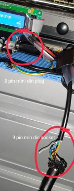
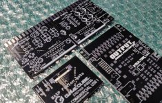
Hmmm, do you have info on how I'd make something like that? I'd love to just us my hd retro cables.

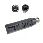
Basically, I really want to be able to plug this into my gcompsw v5.2 so I can get it to output to both my pvm and ossc at the same time. would something like the Bose 9 Pin to 8 Pin Mini DIN Adapter work?
 

Attachments

  • s-l1600.jpg
    s-l1600.jpg
    166.9 KB · Views: 143
Last edited:
I just soldered it all up by hand, an 8 pin mini din male to a 9 pin mini din female.
As for splitting the signal, I want to do the same, and currently use a passive splitter but am waiting for PCBs from elecrow to utilise a double output board using a this video amp. I don't want to name the device because its name is utterly ridiculous but it's on osh park and voultar made it. Search for oshpark voultar double.

It will allow me to output from my Minigun to then output via that pcb to my datapath card and my JVC crt monitor. (Same as pvm but sexier scanlines)

As for the component video output, the guy who created the retrotink is days away from releasing a long awaited scart to component board.i il be buying some asap!
 
Ah, so the 8 to 9 pin converter alone didn't allow you to just plug in the genesis hd retro cable? Also is there a place to follow Mike's scart to component board or is it just going to be on his website?
 
Last edited:
Mike's scart transcoder is available now it cost me about 100$ aud to have one delivered.

The cable I made for Minigun to Sega hd retro cables is just passive , just wire to wire, nothing special. I am making a few more of them, if anyone wants one msg me.
 

Attachments

  • IMG_20190910_221829__01__01_compress62.jpg
    IMG_20190910_221829__01__01_compress62.jpg
    392.3 KB · Views: 248
Isn't that board that's being released a component to RGB scart device? The complete opposite of what we need, RGB to component?
 
Ah, so the 8 to 9 pin converter alone didn't allow you to just plug in the genesis hd retro cable? Also is there a place to follow Mike's scart to component board or is it just going to be on his website?
Just a passive wired converter works well with the hd cables for me, just remember to wire csync from the din8 to composite on the din9. I didn't bother wiring audio on mine and just used the CPS2 stereo RCA into the HD cable 1/4 input.
 
I just received another batch of 2.1 boards in the mail today, if anyone is interested im moving them for $10 AUD each with $1 shipping to AUST and $3-$5 to rest of the world. Inquire by PM. I also got some other boards printed, for splitting SCART signal and an adapter for NGC WASP device, have spares. Share the love.

I cant wait to build my 2.1 board !!!

edit: I am donating a percentage of the sale price of all boards back to @Frank_fjs - gotta support that guy for his excellent work.
 

Attachments

  • IMG_20190911_185425__01_compress76.jpg
    IMG_20190911_185425__01_compress76.jpg
    364.4 KB · Views: 211
I have a stupid question. I’m putting together a custom fight stick and I accidentally shorted +5v to GND through wires to/from the P1 dB15 connector (pin8 to pin 1) which resulted in the pcb emitting a good amount of smoke along the trace back to the power connector. The board is still operable but I wouldn’t expect that to happen?

V1.7

Edit: after looking more closely I can see why that would happen.
 

Attachments

  • 9AFC6559-8029-42F3-A541-C81E875EDE5D.jpeg
    9AFC6559-8029-42F3-A541-C81E875EDE5D.jpeg
    718.8 KB · Views: 231
Last edited:
I have a stupid question. I’m putting together a custom fight stick and I accidentally shorted +5v to GND through wires to/from the P1 dB15 connector (pin8 to pin 1) which resulted in the pcb emitting a good amount of smoke along the trace back to the power connector. The board is still operable but I wouldn’t expect that to happen?

V1.7

Edit: after looking more closely I can see why that would happen.
I mean... if you short +5V and GND, what would you expect to happen :)
Don't do that :P
 
I think subconsciously I'm just looking for a reason to upgrade to the latest version..
 
I accidentally shorted my supergun too when connecting a joystick... fortunately my 42PP0606 PSU stopped quickly and there was no smoke or damaged tracks (but a broken THS7374), the board was apparently not damaged and it works fine.

Since then I don't connect the DB15 metallic case to ground in the supergun. I'd recommend you to connect or disconnect joystick only when the power is off.
 
CPS2 4 player harness. Poorly made as I rushed it however it works nonetheless.

Hoping to update main post soon with all the necessary info.
Do you happen to have the digi-key parts list for the 4p adapter. Understand it's just 34idc and some db15 but wanna make sure I get it right. They may be backordered on some of this stuff so I am not seeing it.
 
I haven't even uploaded the updated PCB yet! =O

There's hundreds of types / brands of db15 connectors on digi, unlikely they'd all be backordered. :)

I'll update things asap...
 
what is the solution for a cheap video cable?
There isn't really one. The solution either requires redesigning the PCB for an MD2 connector, using one of Viletim's adapters or an RGC or similar cable.
 
Make it yourself. Can buy a DIN cable for less than $5, scart housing for $2, DIN connector for $1, 2 meters of 8 core shielded wiring for $2 = $10 cable.

Personally I don't have time for that, and the end result won't be as good as what RGC / RA offer. I'm happy to fork over the cash for someone else to do it, and at a higher level of quality than I can achieve myself. Only need to buy it once and can use it on a variety of systems.
 
I wanted to utilise a Mega Drive 2 cable, but the general consensus was that mini 8 DIN with no components inside is better.

Personally I prefer MD2, because:
  • They're cheaper.
  • More readily available.
  • Most people already own one.
  • Contain the passive components inside the cable - therefore less components on the PCB, cheaper and smaller BOM, quicker to solder.
  • Enables native use of HD component cables.
 
What's the best route for mounting the voltmeter on a 2.1 board? I was thinking standoffs but not sure of the thread size or height ?(
 
M2 standoffs, 5mm high.

Use M2 4mm screws to secure down from top of voltmeter.

Use either M2 4mm screws or M2 nuts to affix from bottom of main PCB, pending whether you grab male to male or male to female standoffs.

4 x nylon M2 washers, 2 x to sit between the bottom of PCB and standoff (1 each side) and 2 to sit between voltmeter tabs.
 
Back
Top