So a question about sync for the Taito F3. I know this probably isn't really the place to ask, but if i were to connect my F3 to my consumer TV using the minigun, could it possibly damage my TV if there's a sync level problem?
You are using an out of date browser. It may not display this or other websites correctly.
You should upgrade or use an alternative browser.
You should upgrade or use an alternative browser.
- Thread starter Frank_fjs
- Start date
@Frank_fjs
the front plate has holes in it to be attached to the jamma edge
but unfortunately I forgot to make cutouts for the nut in the sides. I've just added this in the last revision.
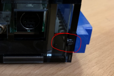
I'll order another case for testing purpurses and after that I'll release the files.
To act as a second anchor point the top and bottom plates needed to be extended in the front, to make channels for the top and bottom standoffs from the front plate (like the sides).
Something like this:


the front plate has holes in it to be attached to the jamma edge

but unfortunately I forgot to make cutouts for the nut in the sides. I've just added this in the last revision.

I'll order another case for testing purpurses and after that I'll release the files.
To act as a second anchor point the top and bottom plates needed to be extended in the front, to make channels for the top and bottom standoffs from the front plate (like the sides).
Something like this:
Last edited:
That is so clever. Thanks for working on this, I'm definitely going to order some when you release the files.
The service and test switches are available with longer buttons, I wonder if there's one high enough to protrude through the top of the plexi holes? Could do the same witb the audio header, use longer pins etc.
The service and test switches are available with longer buttons, I wonder if there's one high enough to protrude through the top of the plexi holes? Could do the same witb the audio header, use longer pins etc.
It should be possible to 3d print some extension and glue it on the button or simply use switches with longer buttons. SInce the front is open you can reach the mono header and service and test Longer headers should also work or go back to the switch option. It's possible to reach the buttons with a flat head screw driver.
Right now I'm adding the additional support for the front plate
Right now I'm adding the additional support for the front plate
You'd need to make an adapting harness, to go from the 20/24 pin ATX to the 6 pin connector on the Minigun, and as you mention ground the ON switch pin, then yes it will work.
Nice enclosure for the M1c. How thick is the plexiglass that you used?Hey Guys,
I've started to "design" a plexiglas-case for the minigun a few days ago.
Disclaimer: I've never done any case modelling or anything like that before. I've just barely managed to design that in Fusion360.
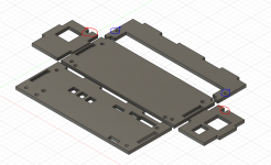
Here are the results for the first prototype:


This is designed specifically to work with the plexi-case I have for my mv1c.
After first assemble I already found two mistakes I need to fix - thats for the next version.
I will release the Fusion files as soon as I have managed to fix the mistakes. After that everyone can modify the files for their needs.
@Frank_fjs: Thank you very much for all your hard work!
- kinox51
Hey there,
here is the latest revision of the case:
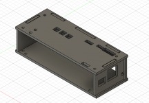
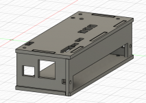
New are the cutouts for the screws in the sidepanels (to mount the Jamma Connector), the support for the front panel at the top and bottom and minor fixes with the mountingholes.
I've just ordered one of these to see it in person and test fit it.
It should work with all revision advanced boards up to v. 2.1 (the last one I have) - the new 4+5 button switch-cutout is not implemented yet. If anybody can give me some measurements I could add it
here is the latest revision of the case:


New are the cutouts for the screws in the sidepanels (to mount the Jamma Connector), the support for the front panel at the top and bottom and minor fixes with the mountingholes.
I've just ordered one of these to see it in person and test fit it.
It should work with all revision advanced boards up to v. 2.1 (the last one I have) - the new 4+5 button switch-cutout is not implemented yet. If anybody can give me some measurements I could add it

https://www.digikey.com/product-detail/en/bourns-inc/3362P-1-102TLF/3362P-1-102TLF-ND/2536611Oh, I like those trimpots a lot!
Which ones are they? Need to put some of those on my Minigun as well.
I'll add them as an option to the BOM.
Hey,
the 2nd revision case hasn't arrived yet, but I've taken the time to add the new switch cutout. Nothing major but here is the new revision
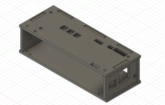
I've taken your measurements @Frank_fjs so when the new case fits the cutout should fit, too.
I'll keep you updated
the 2nd revision case hasn't arrived yet, but I've taken the time to add the new switch cutout. Nothing major but here is the new revision


I've taken your measurements @Frank_fjs so when the new case fits the cutout should fit, too.
I'll keep you updated

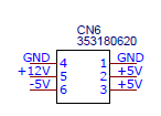
You'll find pinout printed on the underside of the pcb.Could anyone write the proper pinout for the v2.5 6 pin power connector.
pcbs will arrive monday and already super excited. Started on the wiring to make things go faster
And if you want to start directly - look at the "SCHEMATIC_CONNECTORS.pdf" provided in the .zip
Here are pictures of a finished cable:
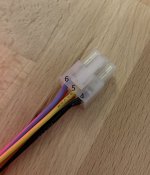
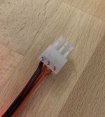
Quoting @acblunden2:
American wring color scheme is:
- Ground = Black
- +5vdc = Red
- +12vdc = Yellow
- -5vdc = Blue (typically)
- Ground = White
- +5vdc = Yellow
- +12vdc = Red
- -5vdc = Brown
Last edited:


