What's new

mathewbeall

Champion
Joined
Nov 6, 2017
Messages
1,714
Reaction score
1,234
Location
Mission Viejo, CA, USA
Hi Folks!

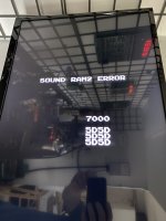
I have a PacMania board that boots up fine, has music - but some sounds are missing. I assume at least when you eat dots there should be sound :)

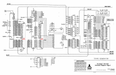
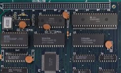
Anyone have an idea of where I can start troubleshooting? Perhaps start by reburning the 2 sound EEPROMS?

Matt
 
Hey, I think if you turn the game on but with the DIP switch configured for service mode (I think its the 1st one), it will do a "rom test", maybe that can yield some useful information?
 
Excellent - I had gone into that after boot (to set options), but didn't realize upon boot that it did a self test. Here is what comes up.

Off to see which chip is sound ram2.
 

Attachments

  • IMG-3419.jpg
    IMG-3419.jpg
    125.7 KB · Views: 106
Both U2 and U3 are right there at the "sound generator" part of the pacmania schematic, don't know which one would be "RAM2",.. but if replacing one doesn't work I'd replace the other. And I had a pic I took from my pacmania board where you can see the 6264 exact model, maybe you find it useful, good luck!
 

Attachments

  • i1.png
    i1.png
    644.4 KB · Views: 111
  • i2.jpg
    i2.jpg
    135.5 KB · Views: 103
So I replaced U3.. upon bootup, basically no sound now - except some samples at the level selection screen.

When I do the test - I get "SOUND CPU NOT RUNNING".

off to look at schematics.

Matt
 
V3 looks to be the sound CPU, I swapped it out with a known working Hitachi 6809 (from a working Namco System 1 board) and still the same issue. Likewise, the sound CPU in the other working board works fine.

Not too sure at this point where to go.

Matt
 
Did you verify the Sound ROMs? If one of them is corrupt then the CPU might be crashing from bad code being fed to it.
Also, if you have a logic probe, check and make sure the Sound CPU Reset line changes state or the CPU won’t start.
 
I will validate the sound roms. I don't have access to a logic probe.

I assume I do this against the mame romset?

Matt
 
You’ll want to get a logic probe eventually (they’re only $20 or so), but in the meantime, check for continuity on the HALT line to the reset circuitry (see schematic) and check continuity on the CLOCK line.
 
Logic probe is ordered. I looked at the schematic and tried to find the continuity test points. On the sound CPU (V3) I see the HALT pin is 40 but I can't see where it connects to - other than pin 2, and then its just a line.

1618642416427.png


For the CLOCK line I see two clocks - Clock A into 35 and Clock B into 34 - and it looks like the clock lines are coming from the H175 chip at S4. ClockA is pin 6 and ClockB is pin 2. Any way I test - I don't seem to have continuity from the chip at S4 to the CPU on V3. I suspect I am doing something wrong.

1618641920920.png
 
I've had a chance to look over the schematics some more on a real computer (rather than my phone). Here's what more details on what to check:

- Pin 37 of the Sound CPU is the Reset line. It should be triggered once to start the CPU executing. It's Active Low, so with a logic probe connected you should see it pulse briefly from high to low then stay high all the time at board startup. The pulse trigger (SUBRES aka Sub CPU Reset) is generated by the Custom 117 chip located at N5 on Pin 51 and then runs to several parts of the board (Schematic page 1). Make sure you read continuity between Pin 37 of the Sound CPU and Pin 51 of the Custom 117.

- Pin 40 is the Halt line. It's tied together with Pin 3 (NMI aka non-maskable interrupt) and Pin 4 (FIRQ aka Fast Interrupt Request). This line will halt the CPU execution temporarily from time to time during normal operation. It's Active Low, but you should see it pulse regularly during normal operation. If the logic probe shows it holding low all the time, then something is wrong with the lines that feed it. Make sure that continuity is confirmed between Pins 2, 4, and 40 on the Sound CPU.
All three pins can be triggered by either the SNDIRQ (Sound Interrupt Request) or FMIRQ (Fast Interrupt Request). SNDIRQ is generated by the Custom 121 located at P2 on Pin 25. FMIRQ is generated by the YM2151 audio generator located at V2 on Pin 2. Both are shown on Schematics Page 6. Verify continuity between Pin 40 of the Sound CPU to both these points.

- As you noted, the Sound CPU uses two clock signals, and those signals are generated by the HC175 chip located at S4. There should be continuity between Sound CPU Pin 34 to HC175 Pin 6, and continuity between Sound CPU Pin 35 to HC175 Pin 2. A logic probe should show regular pulsing activity on both clock lines on the Sound CPU.

Hope that helps. Let me know what you track down.
 
The data bus is connected to a 74ls245 from Fujitsu... You might want to check that one once you get the probe. It's connected to the CUS that I believe handles samples in the System 1 and to the sound CPU as well.
 
I've had a chance to look over the schematics some more on a real computer (rather than my phone). Here's what more details on what to check:

- Pin 37 of the Sound CPU is the Reset line. It should be triggered once to start the CPU executing. It's Active Low, so with a logic probe connected you should see it pulse briefly from high to low then stay high all the time at board startup. The pulse trigger (SUBRES aka Sub CPU Reset) is generated by the Custom 117 chip located at N5 on Pin 51 and then runs to several parts of the board (Schematic page 1). Make sure you read continuity between Pin 37 of the Sound CPU and Pin 51 of the Custom 117.

Now that I figured out chip pin numbering, continuity here is good.

- Pin 40 is the Halt line. It's tied together with Pin 3 (NMI aka non-maskable interrupt) and Pin 4 (FIRQ aka Fast Interrupt Request). This line will halt the CPU execution temporarily from time to time during normal operation. It's Active Low, but you should see it pulse regularly during normal operation. If the logic probe shows it holding low all the time, then something is wrong with the lines that feed it. Make sure that continuity is confirmed between Pins 2, 4, and 40 on the Sound CPU.
Pin 40 and pin 2 on the sound CPU have continuity - which is how I believe it should be looking at the diagram again (not pin 4).

All three pins can be triggered by either the SNDIRQ (Sound Interrupt Request) or FMIRQ (Fast Interrupt Request). SNDIRQ is generated by the Custom 121 located at P2 on Pin 25. FMIRQ is generated by the YM2151 audio generator located at V2 on Pin 2. Both are shown on Schematics Page 6. Verify continuity between Pin 40 of the Sound CPU to both these points.

V2 pin 2 has continuity with sound CPU pin 4. P2 pin 25 has continuity with sound CPU pin 3.

- As you noted, the Sound CPU uses two clock signals, and those signals are generated by the HC175 chip located at S4. There should be continuity between Sound CPU Pin 34 to HC175 Pin 6, and continuity between Sound CPU Pin 35 to HC175 Pin 2. A logic probe should show regular pulsing activity on both clock lines on the Sound CPU.

Hope that helps. Let me know what you track down.
Clock signal continuity looks good also.


Next step - when I get my logic probe - revisit these and see how they act while the board is under power!

Thanks,

Matt
 
Ok - since I have the luxury of having a working board alongside my broken board, I did some tests on the sound CPU, with DIP switch to "1" which is the test mode.

It seems as if pin37 is HIGH after boot, and pin 40 is HIGH.

On my broken unit, pin37 does go back and forth from low to high, but when the "SOUND CPU NOT STARTED" comes up, its goes to LOW. pin 40 (HALT) is still HIGH at this point.

Unless I have the logic probe hooked up backwards, but I have the ground clip hooked to the "GND HOLE" on the side of the board, and the positive clip clipped to a positive side of a capacitor there.

Matt
 
It sounds like you have your probe connected properly. If it didn't you probably wouldn't be getting any readings with the logic probe at all.

Have you tried swapping the B board between your working set and broken set so you can narrow down whether it's the A board or B board that's the culprit?

Anyway, let's break this down:

- On the broken unit, Pin 37 goes low, then high, then holds low after the error.
That means that the Sound CPU is getting correctly reset and is trying to execute code. We can cross that off the list as a possible culprit.

- Pin 40 holds High after the error appears.
Is it holding High the entire time from when the board boots until the error message appears, or is there a little bit of pulsing before the error occurs? This line is Active Low, so it needs to trigger low for the Sound CPU to run. Cross-check the behavior with your working board if need be, but if this line never goes Low then this would be your culprit and we'll next need to examine the components that feed it.

- Is the logic probe showing pulsing on Sound CPU clock pins 34 and 35? They should pulse the entire time the board is booted at least until the error appears.
 
Last edited:
Yep - I did swap the boards, and the problem is for sure in the CPU board as the rom board ran fine with my other working CPU board.

I did see pulsing on pin 34/35 (clocks) the entire time (even after error).

I will check pin 40 (HALT) again - but I believe the behavior was the same on both working and non-working (pin 40 shows high the entire time) but I will check again tonight.
 
Check the data and address buses too. You may have a stuck pin that is causing the processor to crash and it's more likely that is the issue since reset, halt and clock signals are okay(ish).
You should have activity on all data pins and some or all address pins in a working CPU. In this case I would expect activity in all of them.
That's pins 8 to 31 if you don't want to check the schematics ;)
A stuck pin will output a continuous high or low. If your probe has different tones for high or low, it will sound exactly the same as probing VCC or Gnd.
Also, if I recall correctly, that CPU is socketed. You can swap it over from the one on the working board if that's the case. Quick and easy way to check if it's working or not.
 
I just realized that I got my double-negatives crossed. The HALT line is Active Low, so that means if the pin reads High then HALT is inactive and the CPU is operating. The HALT action occurs if the line is pulled Low, so it actually isn't a problem if the line reads High all the time.

I agree with @ic3b4ll that an address or data line is probably getting stuck. From what I'm seeing in the schematics, there's several TTL chips in between the Sound ROMs, Sound RAM and the Sound CPU and if any of them failed then the CPU will process bad data and crash. Check your Sound CPU Address and Data lines for activity - any lines that don't show activity before the diagnostic error message appears are suspect and should be traced to their connected component as per the schematic.
 
Back
Top