What's new
Do you have any idea why the J1-21 pullup isn't connected on the Lydz boards? Your pinout documentation and the assembly guide for the carts makes it seem like at least a 100Ohm pullup is required for the cart to boot properly, but the Lydz carts I've seen never have this pulled up (it's not connected to anything at all, in fact). And when I add the pullup on my cart, it changes the behavior (although it still doesn't give me any meaningful output, heh).
No idea... my PCBs were developed by taking everything but the asic communication logic from an original cart, then when I tried it without the 100Ohm resistor it didn't work. I assume it is a pull up to signal something to the motherboard.

Edit: I think the Microchip site uses some script to give you the download for WinCUPL, disable any popup blocker or ad-blocking you may have running.
It is not great, but the only remaining tool for GAL/PAL programming.
 
I was eventually able to download WinCUPL, but I had to use Microsoft Edge to do it lol...

Unfortunately I don't think I'll be able to salvage the GAL on the board - it's proving extremely stubborn and resistant to desoldering efforts, and I'm concerned that I'll damage the PCB if I work it much more. Part of the problem is that all the through-hole ICs on the Lydz board have had their legs trimmed flush with the bottom of the PCB - so even if I *was* able to cleanly desolder it, it may not make good contact with the reader (I had a tough time trying to dump the ROM from the 27c322 for the same reason, in fact).

I'm a bit disappointed by this as I think it would have been useful to dump the program. Oh well, it is what it is...

So my plan at this point is to essentially completely redo the GAL and Program ROM logic based on the selectable Ketsui / Ketsui Arrange GAL and ROM used for Fluffy boards. I've ordered a couple replacement 22v10s and I'll throw a socket on there to make swaps and experimentation easy. From reviewing the PLD files for the DIY boards (thanks Fluffy!), it's pretty clear that almost all the necessary pins are already routed and only a minor change is necessary to the GAL program + a quick bodge on the PCB.

@Fluffy I do have a question - am I correct to interpret that the INT_P_ROM_OE output pin from your 16v8 GAL program is supposed to be routed to the PGM edge connector's corresponding INT_P_ROM_OE (J1-27)?
 
@Fluffy I do have a question - am I correct to interpret that the INT_P_ROM_OE output pin from your 16v8 GAL program is supposed to be routed to the PGM edge connector's corresponding INT_P_ROM_OE (J1-27)?
Yes, that disables the bios ROM on the motherboard.

Quick tip: Don't get ATF22v10 - they have a different programming algorithm, and some programmers enable the power save. Lattice 22v10 should work.
 
Last edited:
Edit: I think the Microchip site uses some script to give you the download for WinCUPL, disable any popup blocker or ad-blocking you may have running.
It is not great, but the only remaining tool for GAL/PAL programming.
You can also check out GALasm if you ever fancy to rewrite your equations. I used WinCUPL in wine first, but then switched to it as it is open source.
 
I've tried the GAL modifications; while I believe my adjustments to the equations and pinouts are correct, I'm not seeing a meaningful change in output.

While poking around I noticed that none of the PAx_OUT lines are connected except for PA8_OUT, which is kinda weird. I believe most other PGM boards, including the @Fluffy carts, do use these return lines...

So I think my next course of action if I'm going to continue with this plan is to run bodges for all of those lines, which seems slightly insane. I'm extremely curious why it's still having issues at this point, though, so I'm still considering it. :unsure:
 
Last edited:
While poking around I noticed that none of the PAx_OUT lines are connected except for PA8_OUT, which is kinda weird. I believe most other PGM boards, including the @Fluffy carts, do use these return lines...
Interesting, I just copied them from the existing boards. On some boards they go through a small SMD resistor network, so you don't get direct continuity if you check the connector.
I think I traced all the PAx directly to the CPU.
 
20210819_101510.jpg

I got it! 8o


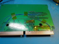
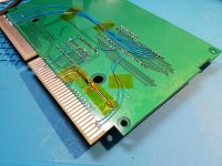
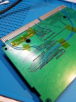
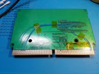
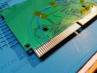
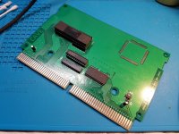
20210819_102046.jpg20210819_102100.jpg20210819_102035.jpg20210819_102041.jpg20210819_102029.jpg

Definitely not the cleanest work; need to practice and improve more for sure. But as my first PCB repair I'm absolutely ecstatic right now lmao.

In total:
  • Removed and replaced main program ROM
  • Removed and replaced program ROM remap GAL
  • Fixed some traces that I broke during the process of those swaps
    :person_facepalming:
  • Bodged INT_P_ROM_OE on the edge connector to the GAL, to disable the motherboard BIOS
  • Pulled up J2_21
  • Rebuilt the entire PAx_OUT bus for returning the address signals back to the motherboard
So effectively what I have done here is rebuild to match the same Program ROM and GAL logic used for the Fluffy kits, which also matches most of the other PGM carts I've looked at for reference during this process.

Based on the pinout weirdness of the original conversion design, it seems to me like there are probably a couple different ways the PGM carts can operate:
  • Certain pins pulled up/down disables the mobo BIOS and changes the boot offset(?) + supported features (maybe ASIC etc.)
  • The address return lines are probably used to trigger things during initial boot (BIOS remap/jumps perhaps?)
  • Lydz original design manages to use the absolute bare minimum subset that is required, only actually routing one of the ten address returns and not using the other pullup/pulldowns at all (they're just left floating in fact, presumably there are pullups/pulldowns to a known state on the mobo)

Now as for why this didn't work originally - I'm honestly not sure. I've documented most of my findings about this cart, but unfortunately I wasn't able to dump the GAL, which is a crucial piece of understanding the puzzle here. Part of what I think is happening with the Lydz design is that it routes one of the address lines through the GAL (PA16) as a 'passed through input', which I haven't seen on other boards. I think it might be doing some weird stuff using that PA16 state in lieu of what would normally be done using the motherboard return lines etc.

In theory this rebuild should also support the Ketsui Arrange dual-boot, just need to add a jumper or switch - I'll try that tonight

Thanks so much for the help @Fluffy ! Really appreciate your feedback during this process.
 
Last edited:
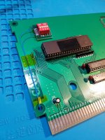
20210819_193938.jpg
20210820_001105.jpg

While testing after work tonight I noticed some strange tearing and graphical errors on the background. Since it only occurred on background tile elements (not sprites) I assumed it was related to the tile ROM; on a friend's recommendation I added some decoupling caps to the board, and reinstalled a bodge capacitor that was across the voltage regulator when I got it initially. That cleared the problem right up - anyone else experiencing a similar issue I'd highly recommend checking decoupling!

20210819_224503.jpg

Once that was sorted, I worked on the dual-boot. Ran a couple wires out to a small perfboard I made up with a DIP switch; the only non-momentary switches I currently have on hand are these 4-gang DIPs. Placing DIP1 in the ON position pulls down the PAGE_SELECT pin of the GAL, and switches to Ketsui Arrange. Unfortunately this is just barely too tall to fit inside a normal PGM cart shell, so I'm currently looking into my options. I think most likely I will simply rewire to a panel-mount switch that I'll install next to the edge connector, but I'll admit there is a lot of convenience to being able to just swap between Ketsui and Ketsui Arrange whenever I want without needing to remove the cart from the motherboard... I'm considering trying to 3D print a modified cart shell with a bit more internal clearance and a cutout for access to the DIPs.

Initially adding this switch caused a lot of garbage graphics and weird behavior, but adding an external pullup (5kOhm) instead of relying on the internal pullup of the GAL (which I think is 100kOhm) cleared that right up.

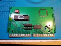
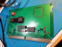
Here are final pictures of the current state of the PROG board; I still need to run a few credits through to make sure that everything works as expected late-game, but so far it seems like I've overcome all the major functional hurdles and made the improvements I hoped to make. Extremely happy to have a positive result for this project, especially after a few big red herrings. Thanks again to everyone here and elsewhere who helped out and showed their support during the process!
20210819_233447.jpg20210819_233454.jpg20210819_233518.jpg20210819_233527.jpg

I've attached the JED and PLD files I used for the GAL, along with notes that explain the pinout. It's functionally identical to the Ketsui/Espgaluda GAL Fluffy uses for his boards, but with some different pin assignments to take advantage of the 22v10 and the existing routing on the Lydz board. Note that this is not a drop-in replacement for the existing GAL, and it requires additional rework to function (100Ohm pullup, bodge to INT_P_ROM_OE, and adding the PAx_OUT lines).
 

Attachments

  • LydzKetsui_Rebuild_GAL_202108.zip
    3.1 KB · Views: 154
Nice work. And damn. That’s a beautifully calibrated monitor you have there mate.
Thank you very much! I spent a while learning how to tune it, and got some help from friends who are more experienced with monitor calibration. I agree that the result is really nice.
 
Received a cracked version of Oriental Legends from Hammy for testing. I was able to get it to work on Fluffys boards.

Unfortunately there is not enough space for all the required GFX roms on the board. This means the game is playable but has graphical glitches due to the missing data. For the full data, the romboard would require an additional 3 slots (2 x A and 1 x B)

I can also add instructions on how to get it running if there is intrerst in that.

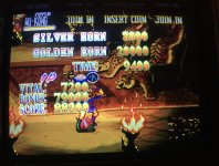
Below are a couple of screenshots of the game running.

IMG_1750.jpegIMG_1751.jpegIMG_1752.jpegIMG_1754.jpegIMG_1755.jpegIMG_1758.jpegIMG_1761.jpeg
 
Unfortunately there is not enough space for all the required GFX roms on the board. This means the game is playable but has graphical glitches due to the missing data. For the full data, the romboard would require an additional 3 slots (2 x A and 1 x B)
Depends on how hardcore you are... the decoders should allow 8 A-Roms and 4 B-Roms, if you piggy-back them and use wires to select select them.
 
It is difficult to find the right balance of cost, size and assembly complexity. Nearly everything modern is only available as fine pitch SMD or even BGA, and I'm not sure how much could be fit into a DIP footprint. I briefly looked at https://www.digikey.co.uk/en/products/detail/alliance-memory-inc/M29F160FB5AN6F2/12180105 , you could fit one on each side of the PCB for 4MB total, but that didn't leave a lot of room for routing, and they are not cheap. Larger Flash are only available in 3.3V, so you'd need to make room for level shifters.
One option would be to do something like CPS3 SIMMs, that could be manufactured in China and used in several projects. Though that would require adapters, and will be difficult to fit into cartridge based systems.
 
if you designed a small PCB with the footprint of a DIP42 that fit 4 of those M29F160s you could have those manufactured in china. so long as they're designed such that they could be programmed in place (maybe using a jumper and/or adapter board). that would offload all of the SMD work to the factory and let people like us just program and install as a DIP replacement.
 
if you designed a small PCB with the footprint of a DIP42 that fit 4 of those M29F160s you could have those manufactured in china. so long as they're designed such that they could be programmed in place (maybe using a jumper and/or adapter board). that would offload all of the SMD work to the factory and let people like us just program and install as a DIP replacement.
I mean, I could fit only 2 of those, and that is with very little room for routing. And placing SMD on both sides of a PCB is another can of worms...

Of course, I could proclaim "IT CAN'T BE DONE!" and count on someone to prove me wrong. :)
 
Back
Top