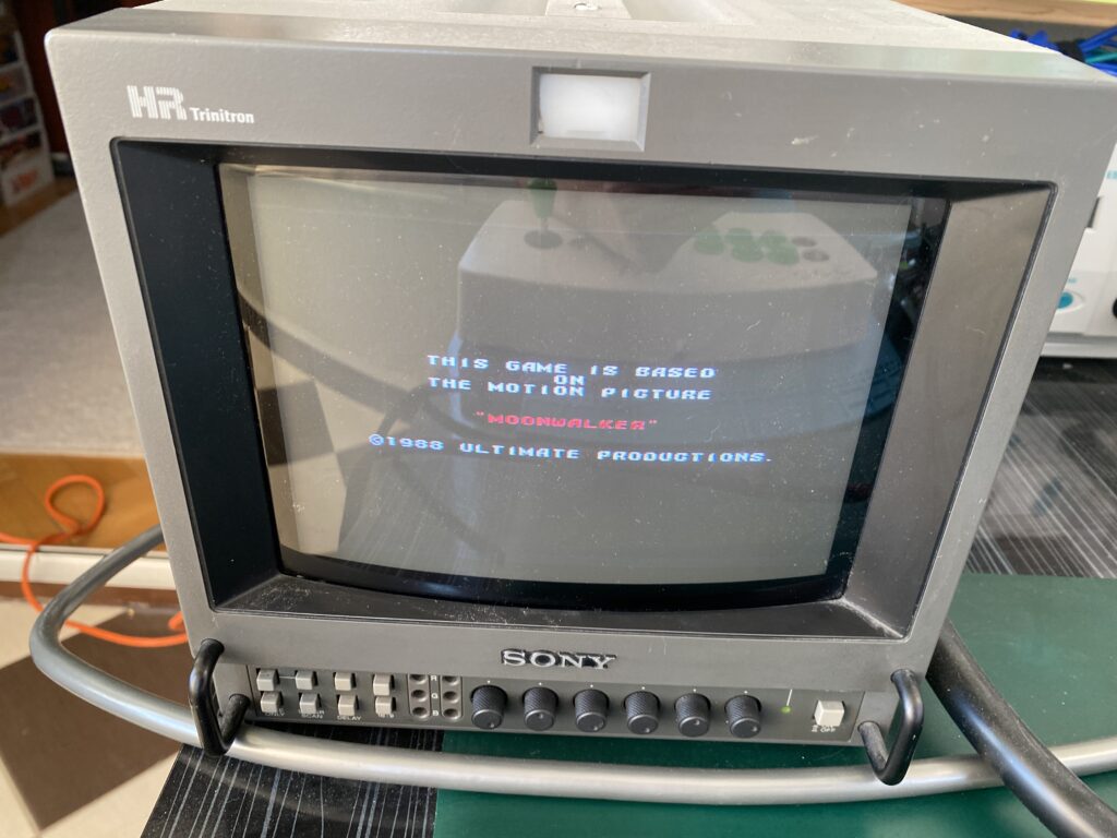
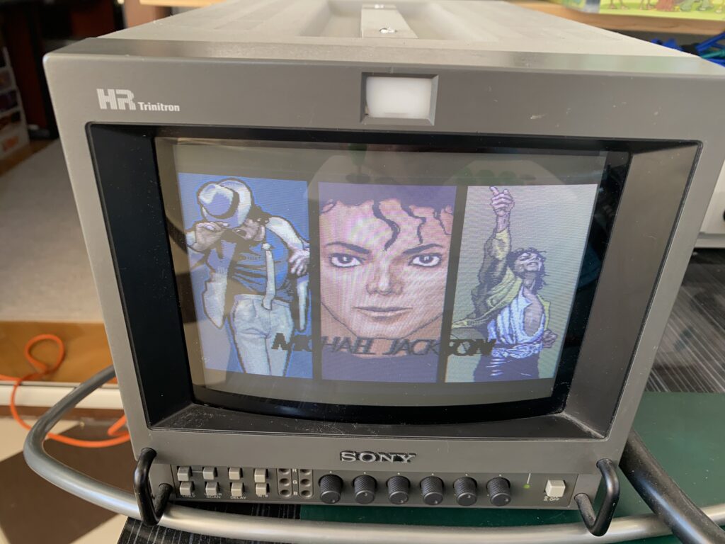
Hello everyone, this time I have Moonwalker – perhaps my favorite game – on my desk.
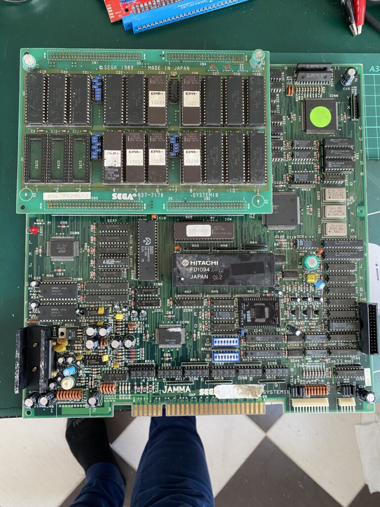
I bought this board “as working” but when powering up, I found out that the board doesn’t boot – it shows no activity at all..
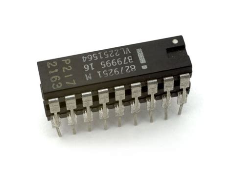
And an IC fell out of the shipping box. But the funny thing is that there is no missing IC on the board.

I bought this board as “working”, but since I bought several boards together and did a package consolidation before shipping, the seller packed these boards naked back-to-back and this is the view…

When we look closely, we can see the damaged traces.


I took out my multimeter, and with it set for continuity testing, I measure the two ends of each trace where a deep scratch passes over it. Fortunately, not every trace is damaged.
There are 2 broken traces at the first scratch location.

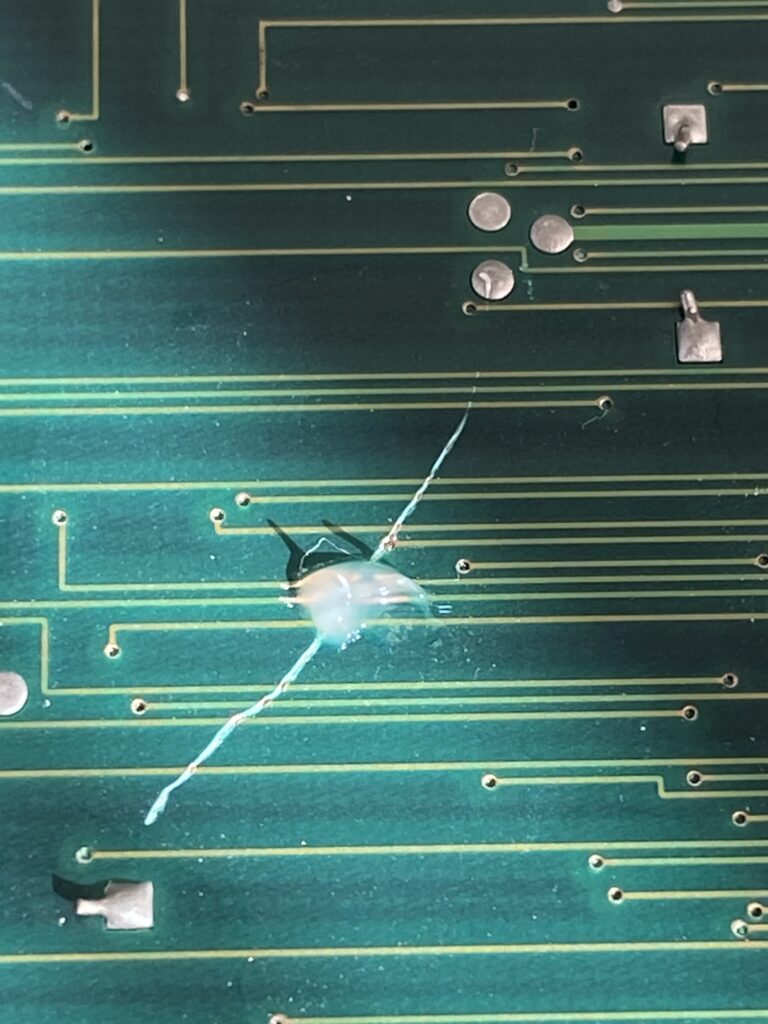
In the second scratched place, we have 3 damaged traces. Moreover, it is a bit more of a winding road.

We’re preparing the operating room now.
In many articles, it is written that “kynar wire” should be used for trace repairs. I couldn’t get it from abroad under this name. This is the wire I found – it is 0.10mm.

If you have any feedback such as this is not suitable, too thin, etc., feel free to say so.
What else do you need? Solder:

What else do you need? Flux:

What else do you need? UV solder mask ink. Some people uses nail polish here, but I prefer to use the professional solution for the problem.

And last but not least, what else do you need? A good eye or a lens or a microscope.
And what’s the last thing you need? Patience like a saint.
First of all, we dig up scratch off the masking a little on the left and right where the trace is broken (enough to expose the copper).

Then add a little flux on top:
Then we solder in a small length of jumper wire to bridge the gap.

How is this procedure done by the masters?
First you apply heat with solder and flux to the bridging wire.
Then you apply flux and solder to each end of the broken trace.
Then you solder one end of the bridging wire to the left side of the broken trace.
Then you solder the other end of the bridging wire to the right side of the broken trace, but while doing this, place something that conducts heat (like a cold solder iron tip) in between so that the heat on the right side does not reach the left side and melt the solder there.
Here’s how it looks after soldering:

I apply solder mask ink on top of it to prevent future damages.

Let’s move on to the second damaged area.
This place made me sweat a lot – especially the curved path in the middle – but I still managed it in the 10-15th attempt without giving up. I am not patient but I am stubborn.

I put an cotton swab next to it so you can see the size of the area I’m working in.

After the repair, we apply solder mask ink to it too.

Time to power up and see how things look. Recall that this was sold to me as a working board, but the photos taken before it shipped to me didn’t have this damage.
I power it up and there’s still no activity – just a black screen.
I bought this board “as working” but when powering up, I found out that the board doesn’t boot – it shows no activity at all..
And an IC fell out of the shipping box. But the funny thing is that there is no missing IC on the board.
I bought this board as “working”, but since I bought several boards together and did a package consolidation before shipping, the seller packed these boards naked back-to-back and this is the view…
When we look closely, we can see the damaged traces.
I took out my multimeter, and with it set for continuity testing, I measure the two ends of each trace where a deep scratch passes over it. Fortunately, not every trace is damaged.
There are 2 broken traces at the first scratch location.
In the second scratched place, we have 3 damaged traces. Moreover, it is a bit more of a winding road.
We’re preparing the operating room now.
In many articles, it is written that “kynar wire” should be used for trace repairs. I couldn’t get it from abroad under this name. This is the wire I found – it is 0.10mm.
If you have any feedback such as this is not suitable, too thin, etc., feel free to say so.
What else do you need? Solder:
What else do you need? Flux:
What else do you need? UV solder mask ink. Some people uses nail polish here, but I prefer to use the professional solution for the problem.
And last but not least, what else do you need? A good eye or a lens or a microscope.
And what’s the last thing you need? Patience like a saint.
First of all, we dig up scratch off the masking a little on the left and right where the trace is broken (enough to expose the copper).
Then add a little flux on top:
Then we solder in a small length of jumper wire to bridge the gap.
How is this procedure done by the masters?
First you apply heat with solder and flux to the bridging wire.
Then you apply flux and solder to each end of the broken trace.
Then you solder one end of the bridging wire to the left side of the broken trace.
Then you solder the other end of the bridging wire to the right side of the broken trace, but while doing this, place something that conducts heat (like a cold solder iron tip) in between so that the heat on the right side does not reach the left side and melt the solder there.
Here’s how it looks after soldering:
I apply solder mask ink on top of it to prevent future damages.
Let’s move on to the second damaged area.
This place made me sweat a lot – especially the curved path in the middle – but I still managed it in the 10-15th attempt without giving up. I am not patient but I am stubborn.
I put an cotton swab next to it so you can see the size of the area I’m working in.
After the repair, we apply solder mask ink to it too.
Time to power up and see how things look. Recall that this was sold to me as a working board, but the photos taken before it shipped to me didn’t have this damage.
I power it up and there’s still no activity – just a black screen.