What's new

rcboosted

Enthusiast
Joined
Jan 17, 2021
Messages
207
Reaction score
93
Location
Los Angeles
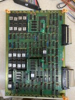
So I picked up a mostly functional 1943 PCB that I want to fix. All the sprites in the game look like they've been chopped vertically and then each stripe offset of each other. For example the P-38 would be chopped into maybe 8 strips, with even numbered strips shifted up, and odd numbered strips shifted down. Same with the enemies, bullets, goodies etc etc. Some searches tells me that it might be a bad rom, but since I have not worked on this board before, I would like some guidance on where to start, before I remove ROMs from an old board.

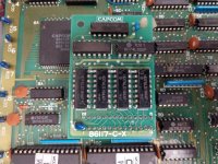
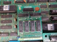
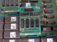
Also, my particular PCB came with these daughter board looking PCB on the bottom board, it goes into vias that looks like should be a for bigger DIP chip. It looks as if Capcom didn't have enough logic chips, so they used a PCB with smaller logic chips to functionally create the chip they need. See pics. Anyone know why it was done this way and some history on it? None of the other 1943 boards I've seen have this.
 

Attachments

  • 8888F712-DA46-4CD5-82E3-A79C95EBDC40 (1).jpeg
    8888F712-DA46-4CD5-82E3-A79C95EBDC40 (1).jpeg
    354.9 KB · Views: 160
  • IMG_20210510_202920330_HDR.jpg
    IMG_20210510_202920330_HDR.jpg
    208.9 KB · Views: 144
  • IMG_20210510_202925147_HDR.jpg
    IMG_20210510_202925147_HDR.jpg
    201.3 KB · Views: 111
  • IMG_20210510_202929715_HDR.jpg
    IMG_20210510_202929715_HDR.jpg
    222.8 KB · Views: 153
Well, the easiest place to start is to carefully remove each EPROM/ROM from its socket, check the legs for rust or tarnish, blow out the socket with compressed air and reinstall the EPROM. If you’re lucky, one of the EPROMs just has a bad connection. If you do find tarnish on an EPROMs legs, you can scrub it off with an emery board.

Also, disconnect the ribbon cables connecting the two boards together, then firmly reconnect them.

It’s very likely that one of your EPROMs had gone bad. The best way to check for that is to dump each EPROM with an EPROM programmer and then compare the checksum of the dumped file against MAME. If the checksum doesn’t match for a particular ROM, you can program a fresh EPROM with the programmer.

There’s a thread on selecting an EPROM programmer here if you don’t have one already:
https://www.arcade-projects.com/thr...de-hobbyists-to-have.4046/page-19#post-274453

Regarding the daughterboard, you explained the reason for it already - a Custom chip was supposed to go there, they didn’t have any on hand, so they substituted the TTL logical equivalent. They do show up from time to time in pre-CPS1 Capcom boards.
 
Last edited:
The litte daughterboards are TTL replacement of the '86S100' custom IC :

86S100_original.jpg


I reproduced it time ago making two versions (one with SMD TTL, the other with a small CPLD)

86S100_repro_laste_revision.JPG
86S100_CPLD.jpg


I think Capcom chose to use TTL replacement for a better reliability (the 86S100 fails quite often).I have both revision of board, they play eactly the same way.

As for your sprite issue, it's most likely due to a faulty '86S105' custom IC (the one in PLCC84 package located on bottom board).This is a welll-known very prone to failure part.I'm studying a replacement, stay tuned!
 
Well, the easiest place to start is to carefully remove each EPROM/ROM from its socket, check the legs for rust or tarnish, blow out the socket with compressed air and reinstall the EPROM. If you’re lucky, one of the EPROMs just has a bad connection. If you do find tarnish on an EPROMs legs, you can scrub it off with an emery board.

Also, disconnect the ribbon cables connecting the two boards together, then firmly reconnect them.

It’s very likely that one of your EPROMs had gone bad. The best way to check for that is to dump each EPROM with an EPROM programmer and then compare the checksum of the dumped file against MAME. If the checksum doesn’t match for a particular ROM, you can program a fresh EPROM with the programmer.

There’s a thread on selecting an EPROM programmer here if you don’t have one already:
https://www.arcade-projects.com/thr...de-hobbyists-to-have.4046/page-19#post-274453

Regarding the daughterboard, you explained the reason for it already - a Custom chip was supposed to go there, they didn’t have any on hand, so they substituted the TTL logical equivalent. They do show up from time to time in pre-CPS1 Capcom boards.

Thank for the suggestions, I will give reseating the EPROMs and ribbon a try! Currently working through some burner problems on my TL866, so I won't be able to dump the contents for a bit. So this is the best I can do right now.

The litte daughterboards are TTL replacement of the '86S100' custom IC :

86S100_original.jpg


I reproduced it time ago making two versions (one with SMD TTL, the other with a small CPLD)

86S100_repro_laste_revision.JPG
86S100_CPLD.jpg


I think Capcom chose to use TTL replacement for a better reliability (the 86S100 fails quite often).I have both revision of board, they play eactly the same way.

As for your sprite issue, it's most likely due to a faulty '86S105' custom IC (the one in PLCC84 package located on bottom board).This is a welll-known very prone to failure part.I'm studying a replacement, stay tuned!

Very interesting project you have on the repro TTL custom IC! Projects like these keeps these boards from going into the trash heap and saving them.

I'm both excited and sad to hear about the possibility of my sprite issue. Excited because there could be a replacement. Sad because it isn't just a simple Eprom or logic IC fix. I wonder where I can keep my eye out for when you're finished with the replacement?
 
Back
Top