Finished this last year, haven't had a chance to do a full blog article but I thought some people here might like it:
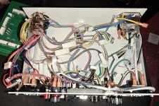
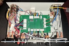
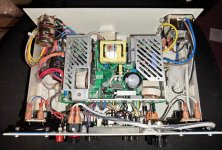
I started this project 12 years ago if you can believe it, made the wiring diagram, bought most of the parts, then when it came to getting the panel made so I could actually put things together - it turned out to be too expensive to get the metal cut. Fast forward 12 years and you can just upload svg files and receive cut metal in the post for £50. I redesigned some of it due to more experience, totally re-did the PCB to match and to line up with the PSU posts, and I've skipped on wiring the 5v adjust up for now. I'm still debating on whether I can do that with a connector or whether it's soldered wires time which would make dissassembly harder, it's all intended to be modular for maintenance. That said I'm seeing little voltage drop except on the very largest PCBs so maybe it's just fine to leave it like this. I'll have a detailed write-up on my blog at some point but here are some photos from along the way.
Features: 2x joystick inputs (6 buttons plus coin/start), external kick harness plus stereo audio input, left audio channel switchable between jamma / jamma with spk- on common ground / external, audio output switchable between internal speakers and out of the AV port at the back (another centronics), AV port has pure TTL pins and scart adjusted pins with a potentiometer for brightness adjust around the back where the loom comes in, up to 6 buttons across jamma are supported (pin 27 6/gnd), button 5 can switch to a toggle for neo geo game select, video ground from jamma or common ground, test button is push down to activate or lift to latch for Namco etc, banana ports to plug a logic probe into the front, uses a proper IEC port for power and has an external fuse holder. This did result in a lot of wires and lots of connectors since you can remove almost every part or section without desoldering anything.


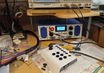
The little joystick is an Aliexpress special, it was analogue so I cut the outer track in the potentiometers and rewired it all, sloppy to use but it works fine. Edit: I now have a second controller made out of a USB megadrive style pad.
The colour scheme I picked to go with my giant eprom eraser.

I started this project 12 years ago if you can believe it, made the wiring diagram, bought most of the parts, then when it came to getting the panel made so I could actually put things together - it turned out to be too expensive to get the metal cut. Fast forward 12 years and you can just upload svg files and receive cut metal in the post for £50. I redesigned some of it due to more experience, totally re-did the PCB to match and to line up with the PSU posts, and I've skipped on wiring the 5v adjust up for now. I'm still debating on whether I can do that with a connector or whether it's soldered wires time which would make dissassembly harder, it's all intended to be modular for maintenance. That said I'm seeing little voltage drop except on the very largest PCBs so maybe it's just fine to leave it like this. I'll have a detailed write-up on my blog at some point but here are some photos from along the way.
Features: 2x joystick inputs (6 buttons plus coin/start), external kick harness plus stereo audio input, left audio channel switchable between jamma / jamma with spk- on common ground / external, audio output switchable between internal speakers and out of the AV port at the back (another centronics), AV port has pure TTL pins and scart adjusted pins with a potentiometer for brightness adjust around the back where the loom comes in, up to 6 buttons across jamma are supported (pin 27 6/gnd), button 5 can switch to a toggle for neo geo game select, video ground from jamma or common ground, test button is push down to activate or lift to latch for Namco etc, banana ports to plug a logic probe into the front, uses a proper IEC port for power and has an external fuse holder. This did result in a lot of wires and lots of connectors since you can remove almost every part or section without desoldering anything.


The little joystick is an Aliexpress special, it was analogue so I cut the outer track in the potentiometers and rewired it all, sloppy to use but it works fine. Edit: I now have a second controller made out of a USB megadrive style pad.
The colour scheme I picked to go with my giant eprom eraser.

