What's new

XtraSmiley

Legendary
Joined
Sep 18, 2016
Messages
4,496
Reaction score
3,839
Location
Washington DC
So I just got this PCB from a seller I consider reliable, but he's far away and return shipping would kill this deal as it's an inexpensive PCB to begin with. I am sadly not near anything I can do much testing with, but hoping someone may be able to give a hint based on image.

Using a HAS and OSSC to test and the only unusual thing is I have the PS set to 5v (on the HAS LED) and this game booted at 4.7 and OSSC would not sync at all. I thought it was unusual, but slowly gave it more power, about 4.85 until it booted. On my other PCBs this setting is like 5.15 so it's losing power some where and it's not a big PCB.

Anyway, the ROM checks pass and sound and gameplay seem fine, but enemy sprites are striped.

https://ibb.co/vz6LzKh

https://ibb.co/9NrVrbz

Any quick ideas? The power draw being high high indicate something, but without testing equipment, I realize this is a shot in the dark. I can provide a pic of the PCB, if it helps, but it's pretty clean from my eyeball check.
 
Well, checking around and it seems these boards have a tendency to have bad RAM chips in the corner. So, going with that, two questions.

1. Can I just buy one and piggy back it one at a time per RAM chip to see if the problem clears up, or will I have to desolder them one at a time?

2. I've never bought a RAM chip, can someone point it out online so I can see what the cost and offer the seller refund that amount?

I also did't do my usual EPROM re-seat, but I'll leave the for the next time I pull the board out.
 
I’m just getting to bed here, so I can only answer your first Q at the moment.
1) yes, you can try piggybacking a RAM chip and see if it makes a difference.

FWIW, I had a Fire Shark board with a similar problem and it ended up being a bad sprite ROM chip. Video of the diagnostic procedure here:
View: https://youtu.be/2PAtTIAijeA
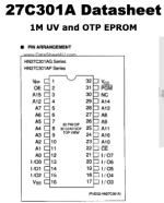
sir , where is writed about the 1m eeprom is needed to use a non-jedec one for that o17_01.1d file ? i'm just curious to see why you used 301's instead 010 :happy: (i try to figure it out and learn)
 
a logic probe ($20-$30) is worth the small investment. Piggybacking may work in some situations, like if an output line is dead on the original chip and the piggybacked chip drives the output. but otherwise there are many situations where piggybacking won’t help even if the chip you’re doing it on is bad. For example if that same output isn’t dead but being pulled high, then the piggyback chip will also end up being pulled high.
 
sir , where is writed about the 1m eeprom is needed to use a non-jedec one for that o17_01.1d file ? i'm just curious to see why you used 301's instead 010 :happy: (i try to figure it out and learn)

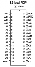
The pinout between the 301 and 010 are pretty much identical except that Pins 2 and 24 are flipped between the two of them. Those pins are Address 16 and Output Enable, so you have to follow the traces for the pins and see if it leads back to addressing circuitry or enabling circuitry. So it does take some sleuthing, although determining which pin is Address 16 and OE is straightforward if schematics are available for the board you're working on.

Another strategy is to look over repair logs for games that use the same hardware and had similar issues. In this case, @caius wrote a repair log for Outzone where he mentions replacing failed sprite mask ROMs with non-JDEC EPROMS: https://www.jammarcade.net/out-zone-repair-log-7/

Screen Shot 2021-03-03 at 7.26.13 AM.pngScreen Shot 2021-03-03 at 7.26.29 AM.png
 
a logic probe ($20-$30) is worth the small investment. Piggybacking may work in some situations, like if an output line is dead on the original chip and the piggybacked chip drives the output. but otherwise there are many situations where piggybacking won’t help even if the chip you’re doing it on is bad. For example if that same output isn’t dead but being pulled high, then the piggyback chip will also end up being pulled high.
Thanks, I'm wiling to make that investment. Do you mind pointing to one on Amazon that you think is the bees knees so I can pull the trigger. I assume that since there is a power drop on this board, something is bad on it.

Also, what's he RAM I'd need to pick up for repair of this one, is there a good site for them?
 
I got an RSR 610B off ebay for $20, but you can buy anything on the market. I like having the cheap speaker so I can hear high/low/toggling without looking at the light. These things aren't rocket science or precision tools in any way shape or form. they basically just have a setting for your high voltage level (TTL / CMOS) then they are just beeping/flashing "high" when they are seeing that high voltage, "low" when it's below that ttl/cmos threshold voltage. Most of the time it's toggling so you see (or hear) the toggle between high and low very quickly. Or, of course, they don't do jack shit if the line is dead. To start out I usually just poke around a relevant section (like if it's not booting, that'd be program roms or work ram) looking for dead lines or lines stuck high/low, and I make sure the line isn't supposed to be stuck high/low by looking at the chip's pinout. Lines like CE (chip enable) are supposed to be always-high or always-low. Power is obviously always high, ground always low, for example.

Take all this with a grain of salt, my batting average for fixing non-booting boards is very bad. If they're booting, I do better ;)

I dunno about the ram, I haven't seen that board. it probably has multiple types of ram for different reasons. If you find a bad chip, then you can look up that chip online and buy from wherever has them. digikey and mouser are great for equivalents if they're in production. Otherwise I'd take it from a scrap board or buy from china/ebay. A lot of manufacturers have different product names for the same chip, but you can usually find them all by searching the generic ram # like "6264" for 8kx8 sram. MAME is my first stop, when I can't read anything on the chip, to see if someone has diagrammed which chip it might be.
 
So, I still don't have a probe from Amazon, but I did use my probe from my mom. Took a closer look...

https://ibb.co/58nLGGm
https://ibb.co/N79dP6n
https://ibb.co/9wTdBF7
https://ibb.co/bNxgzL2
https://ibb.co/9G8g8FY

So I will have to grab at least one RAM. These things must have had a fault in the mix at the factory!

Anyway, I'm a noob at this, my first repair attempt and I'd like to install a socket for this RAM. How do I know what socket size to buy? I took a measurement with my new free tool.

Pinging @twistedsymphony since he's done this exact repair, for advice (and socket and chip info, cheap source?)
 
Just saying that ibb image thing is garbage, just upload the photos here directly!

count the pins, these fit very standard footprints for sockets. Cheap is slow boat from eBay. The only goof up you can make is that for some pin counts you have wide or narrow. But that’s easy to see.
 
I'd like to install a socket for this RAM
why?

How do I know what socket size to buy?
count the pins

Personally I only ever socket chips if
1. the chip can be programmed (PROMS, EPROMs, EEPROMs, PLDs ,etc)
or
2. I'm experimenting and want the ability to try different chips or run without the chip

for repair work, logic ICs, RAM, and other non-programmable stuff just get soldered back in without a socket.
The only exception might be CPUs... but that's mostly because there a boat-load of pins and it makes future troubleshooting easier.

But don't listen to me... I'm pretty crap at repair work.

--------------
If you do want to use a socket for whatever reason 99.9% of the through-hole chips are 2.54mm pitch... similarly 99.9% of the sockets on the market are also this pitch. you can get yourself a kit like this if you think you'll need more in the future: https://www.amazon.com/OCR-Sockets-...jbGlja1JlZGlyZWN0JmRvTm90TG9nQ2xpY2s9dHJ1ZQ==

Sockets are going to be less reliable than soldering the chip in directly, that's why re-seating chips and connectors is a thing people do when troubleshooting.
Also there are different kinds of sockets
single wipe - means it only has a contact on 1 side. these are garbage but I also don't think they even make them anymore.
double wipe - means it has contact on both sides of the pin, these are the cheapest and they work very well.
machine-pins - these have circular pins, they're more expensive than double wipes and IMO they're not as good, they're probably better for weird modules that have circular pins but most chips have flat pins and are better suited for double-wipe sockets IMO.
 
Last edited:
Just the info I was looking for!

The reason for the socket is that I'm grabbing a few used modules off of ebay and seeing how this particular chip is shit and likes to crumble, I want to be able swap it out easier later. Also, used might mean it doesn't work and I don't want to find out after I solder it in!

Isn't it odd that even though I have the other part number from you, it's that same area that has the chips break off like that?
 
Back
Top