What's new

Hitachi GMK 29FJ Help

Kidkaos

Champion
Joined
Feb 7, 2019
Messages
1,259
Reaction score
1,262
Location
Northern California
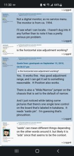
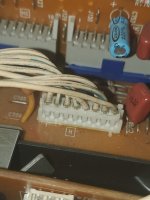
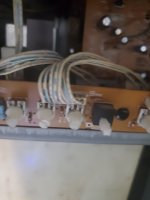
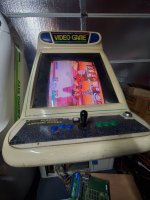
I recently purchased a Pony Mark IV, it has a Hitachi GMK 29FJ
Colors look nice, picture finally synced for me, BUT now I have this weird slant. None of the pots on the remote board fix it. I don't read Japanese and the manual doesn't seem to have any TRAP pot or PARA like the NANAOS/WGs do. Unless I'm missing it, does someone know which of the 3 daughter cards handle the TRAPEZOID pot if there's even such a thing on these?
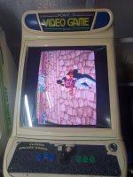
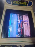
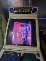
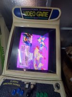
Any help is appreciated. See slant on the upper right side
 

Attachments

  • 20221113_225454.jpg
    20221113_225454.jpg
    173.1 KB · Views: 118
  • 20221113_230747.jpg
    20221113_230747.jpg
    175.4 KB · Views: 120
  • 20221113_230745.jpg
    20221113_230745.jpg
    177.9 KB · Views: 108
Last edited:
Is it just on the top?

If it is, it's a cap issue.
Yes, just the top there.
It has all new caps. I'm doubtful
Looks more like pincushion no?
I also found this, but I don't read Japanese and idk what lone pot it could be "Saido Pin"
 

Attachments

  • Screenshot_20221113-233004_Chrome.jpg
    Screenshot_20221113-233004_Chrome.jpg
    128.6 KB · Views: 87
So I haven't been able to locate the "Saido Pin" pot

But I did mess around with this for a bit and found that messing with this H hold wire slightly brought the "bend" back straight-ish but doesn't 100% solve the entire curve. Could it be that this short wire is "bad" cracked inside? Or will this still be a bad cap somewhere on the video signal line section?
 

Attachments

  • 20221114_234631.jpg
    20221114_234631.jpg
    126.1 KB · Views: 75
  • 20221114_234200.jpg
    20221114_234200.jpg
    78.4 KB · Views: 81
I would check the solder joints for the connector first.

There's no labels for most of the pots on this chassis. I think the guy on Arcade-Museum has a replaced chassis and was just reading the sticker on the monitor frame. I think he has a GMK-29FS.

I want to say the two pots (that are to the side) on the middle daughter board adjust geometry, but I could remember wrong.

It has all new caps. I'm doubtful

Really? There's a million caps on the thing. I did one a few months back. I never want to do another one again.
 
So I haven't been able to locate the "Saido Pin" pot

But I did mess around with this for a bit and found that messing with this H hold wire slightly brought the "bend" back straight-ish but doesn't 100% solve the entire curve. Could it be that this short wire is "bad" cracked inside? Or will this still be a bad cap somewhere on the video signal line section?
Sometimes a voltage that is incorrect can cause a curl or issue like that at the top of the screen.

I agree with Nem, check the solder joints on the connector. If you are seeing a direct correlation between touching the wire and the problem being effected I say you are on the right path.

If you have the schematic, look up the values associated with the potentiometer that controls Horizontal hold, and use a DMM to cross reference that with the values that the potentiometer is actually reading. (Leg 1 to 3 is the max resistance, leg 1 to 2 is the current resistance based on position of pot). Unlikely, but maybe a bad pot not giving the proper resistance needed.

You also mentioned it has all new caps? Not sure if you did the shotgun or someone else did but theres always a chance that there was something with an incorrect value that was replaced so I would go over anything in the deflection circuit pertaining to H hold and see if all value match the schematics.
 
Thanks for your input. I figured out the pot is bad. I've messed with it and the solder joints are pristine, my dmm reads no broken traces and after messing with the pot i got the picture to un-roll and be fine for about 3-5 minutes then it curls back to original.
Anyone know what pot value these used???
 

Attachments

  • 20221115_220033.jpg
    20221115_220033.jpg
    165.7 KB · Views: 96
  • 20221115_220425.jpg
    20221115_220425.jpg
    164.9 KB · Views: 76
Which pot are you talking about?

You can also try spraying contact cleaner on the pot.
 
Thanks for your input. I figured out the pot is bad. I've messed with it and the solder joints are pristine, my dmm reads no broken traces and after messing with the pot i got the picture to un-roll and be fine for about 3-5 minutes then it curls back to original.
Anyone know what pot value these used???
Yeah if you have some Deoxit D5 use that to clean the pot off like Nem said. Sometimes , more often than not, that will fix the issue. But if not…

I looked all over and couldn’t find a schematic for the chassis either. What is the resistance from leg 1 to 2 at max? That will give you an idea a ballpark of where you need to be. What I would do is measure the other adjacent pots from leg 1 to 3 and see what they are rated at. Let’s say they are all 2k - 4k pots, I would just get something in that range to replace it. The only risk you run is not being able to “trim” the value as accurately if you pick a resistance that is too large. I.e. if the stock pot was 4k and you get a 10k your going to have a hard time dialing in finer value or blow right past the setting you want.
How would I measure resistance? What setting do I set the dmm to? My dmm is basic and I'm not super sure what to set it at to measure resistance.
 
How would I measure resistance? What setting do I set the dmm to? My dmm is basic and I'm not super sure what to set it at to measure resistance.
It usually looks like a little Ohm, just put other lead on leg 1 and one lead on leg 2 or 3.
 

Attachments

  • measuring-resistance-digital-multimeter.jpg
    measuring-resistance-digital-multimeter.jpg
    71.3 KB · Views: 79
Anyone have an extra remote board for this chassis? I fucked mine up. Burnt the trace, chassis doesn't come on anymore.
I bought a few different trimmer pots and none were fixing the issue. I got the bright idea to swap a working one with the same value and in the process I burnt the pads now chassis doesn't come on, fun stuff.
 
Back
Top