Big_P Big_p
Professional
These guys are actually not too bad if you change out a few things to fix some of the reliability problems. Picture is clear on a good tube but there is no degaussing circuit or place to plug it.
I documented the steps to rebuilding one of these here: Post in thread 'Chandy Cab Restoration' https://www.arcade-projects.com/threads/chandy-cab-restoration.33621/post-463044
And just wanted to create a thread for anyone looking at these in the Monitors section of the forum. I don't think I documented (or remember) what the rectifier diodes were replaced with exactly but they went up to 3A and they were something pretty standard from a reliable manufacturer.
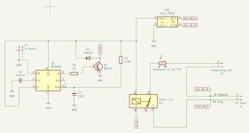
I have been considering designing a basic degaussing circuit for the Chandy and if I do I'll document it here.
I documented the steps to rebuilding one of these here: Post in thread 'Chandy Cab Restoration' https://www.arcade-projects.com/threads/chandy-cab-restoration.33621/post-463044
And just wanted to create a thread for anyone looking at these in the Monitors section of the forum. I don't think I documented (or remember) what the rectifier diodes were replaced with exactly but they went up to 3A and they were something pretty standard from a reliable manufacturer.
I have been considering designing a basic degaussing circuit for the Chandy and if I do I'll document it here.