What's new

HornheaDD

Professional
Joined
Apr 28, 2021
Messages
411
Reaction score
321
Location
Texas
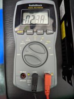
I just got a new arcade PSU and have wired it up to be plugged into the wall. Before I plug any boards into it, I want to try and dial it in to as close to 5.0v as I can. I freely admit that I'm not an EE but I have had this MM for quite a while (even replaced the battery today) and Im just not making heads or tails out of this. Here are some images:

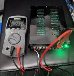
Ive got the PSU plugged into power, with the + probe in the 12v port and the - probe in the +5.
As you can see my readout doesn't seem to make sense (at least not to me) Turning the adjustment knob does make a difference but it doesn't get me anywhere near 5v.

MM_Hooked.jpg

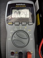
Here is my MM selected to direct current readout:

Hooked2.jpg

And to AC readout:


Hookd 3.jpg


I thought maybe the battery is dead, but this now has a brand new 9V battery in it. Im not certain what I'm doing wrong here. I've used this to find voltage on several boards in the past as well as just to test continuity (which does seem to work properly).

I'm sure its something mundane I'm missing but I can't seem to figure this out. My next step would be to get a new MM but not if I don't need to.
 
Hm, ok. I dont have anything put together to do that just yet but I was following this vid: (its cued to where hes about to test)

View: https://youtu.be/zebdqf9CCMA?t=470


He tests the PSU without a load (and no field ground connected) and seems to get a proper reading.

EDIT: Also ive tried reading from another good 9V battery and don't get a proper reading either. I have a feeling this thing might be burned out after all this time.
 
EDIT: Also ive tried reading from another good 9V battery and don't get a proper reading either. I have a feeling this thing might be burned out after all this time.
Ok yeah that doesn't look good for the meter. Your PSU should at least be in the ballpark without a load hooked up, but when it does come time to dial it in, you will want a board hooked up.
 
So I tried my brother in law's MM and Im still lost.

Measuring from a 9v battery works fine, but I have no idea what's going on. at one point I flipped the probes and was able to get a reading of about 4.7, but when I went to adjust the knob, it went to zero.

Strange thing is if I try to read a wall socket with his meter, it reads 120+ v. So that means its reading fine.
Same for when I place the probes on the black and white leads into the power supply, I get 120+ V. But output seems to be wonky. Could this be a bad power supply?

Here's a short vid. The same thing happens if I put the + probe in the 12 or the - one.

View: https://www.youtube.com/shorts/Z1u0u8ooVGk
 
Power supplies have to be tested under load. Turn 5v most of the way down, hook up something that draws power, and measure/adjust from there.
+1 for this - huge variety of power supplies and implementations out there, but some (many) of them need to have a certain level of load to supply an accurate reading, or in some cases to generate any current at all.

Meanwell in particular are notorious for this.

What's the make/model of the power supply you are testing?
 
Correct me if I'm wrong and maybe I been using my dmm wrong for many year but.....don't you put the black comm lead on GROUND and red lead on +5v or whatever lead you want to read? If I put my Black comm lead on 12v audio and +5v it wouldn't read either....
 
with the + probe in the 12v port and the - probe in the +5
Why would you do that?
+ probe goes to the voltage you want to test, - probe to gnd.

Also when measuring AC voltage (like a wall outlet) you need to set the meter to AC. The power supply +5, +12, and -5 are DC voltage.

Also as everyone has said, most power supplies need to be tested with a load. Just turn it all the way down, connect it to a game, then measure and adjust it while it's on.
 
Not trying to offend but I would take a moment to watch a few youtube videos about how to use Multimeters we all start somewhere.
It is a little cryptic when your first ever starting with this stuff but its really easy when you understand what is happening and the symbols.

Anyways
You need to set the meter to DC mode which has the V with a solid and dashed line on it (one position below in your video).
When you change your meters mode in the video you will notice the squiggle ~ this is for AC alternating current like what comes out of your wall.
You wont see anything DC really when set to AC mode. Your power supply takes AC from the wall and converts it to DC 5V 12V etc, something useable for electronic boards.

I also would not change modes or turn on your multi meter while power is applied to it but thats just me.

Also and maybe I am wrong as someone else pointed out, it looks like you have your red positive probe on 5V and your black negative probe on 12V.
This really is not advisable at all if this is what is happening. You are shorting your 12V rail to your 5V rail.

The screw terminal marked GND is where your black / Com probe from your meter goes and your Red probe from your meter goes to the voltage you wish to check (IE + 5V DC).
THIS IS FOR DC measurements not AC

Current / Voltages flow from positive to negative / GND. So if you dont have a ground source you wont have a path for electricity to flow properly.
Think of it this way your multimeter is inbetween the path of flowing electricity and your meter is sampling/measuring that flow. So you need to have your source of electricity 5V flowing through your meter to a ground GND.

You should also have something connected to your power supply that is pulling electricity from it maybe a cheap board you dont care about or something.
Some power supplies will not output or do not output fully unless it has a load (something pulling electricity from it)

Your output you measure from the power supply can also vary a little bit depending on the board connected to it because the demand/load of that board can be different. This is another reason to check this way.

I hope that helps you


Edit:
I just realized as well you said you put one probe on +12v and one on -?
Some power supplies have negative voltage terminals. This actually is not a negative in the sense it is ground. Rather its outputting a voltage at a negative value. So for something like -5V DC or -12V DC you still need those to source a ground. IE -12V is not ground for +12V
 
Last edited:
Not trying to offend but I would take a moment to watch a few youtube videos about how to use Multimeters we all start somewhere.
It is a little cryptic when your first ever starting with this stuff but its really easy when you understand what is happening and the symbols.

Anyways
You need to set the meter to DC mode which has the V with a solid and dashed line on it (one position below in your video).
When you change your meters mode in the video you will notice the squiggle ~ this is for AC alternating current like what comes out of your wall.
You wont see anything DC really when set to AC mode. Your power supply takes AC from the wall and converts it to DC 5V 12V etc, something useable for electronic boards.

I also would not change modes or turn on your multi meter while power is applied to it but thats just me.

Also and maybe I am wrong as someone else pointed out, it looks like you have your red positive probe on 5V and your black negative probe on 12V.
This really is not advisable at all if this is what is happening. You are shorting your 12V rail to your 5V rail.

The screw terminal marked GND is where your black / Com probe from your meter goes and your Red probe from your meter goes to the voltage you wish to check (IE + 5V DC).
THIS IS FOR DC measurements not AC

Current / Voltages flow from positive to negative / GND. So if you dont have a ground source you wont have a path for electricity to flow properly.
Think of it this way your multimeter is inbetween the path of flowing electricity and your meter is sampling/measuring that flow. So you need to have your source of electricity 5V flowing through your meter to a ground GND.

You should also have something connected to your power supply that is pulling electricity from it maybe a cheap board you dont care about or something.
Some power supplies will not output or do not output fully unless it has a load (something pulling electricity from it)

Your output you measure from the power supply can also vary a little bit depending on the board connected to it because the demand/load of that board can be different. This is another reason to check this way.

I hope that helps you


Edit:
I just realized as well you said you put one probe on +12v and one on -?
Some power supplies have negative voltage terminals. This actually is not a negative in the sense it is ground. Rather its outputting a voltage at a negative value. So for something like -5V DC or -12V DC you still need those to source a ground. IE -12V is not ground for +12V


No offense taken, I appreciate the breakdown.

The video I linked to shows the guy placing the probes in the first two terminals. While my PS is not a suzo happ ( @hatmoose its a RetroArcade MH-16A) it has the same terminal set up as the one in the video.

I was wanting to test it without a board connected because I only have three available to try, two of which I don't want to even run the risk of burning out, and the other I know is a busted board (Neo Geo 1 slot with an Issue I cant recall at the moment). I wanted to get as close to 5 as possible then install it fully and then really put it through a test. If it blows the Neo, no big loss. But I dont want it to even risk blowing the other two boards, a PGM and a Primal Rage.

In the video I posted (of me) I do have the probes reversed, but at first as you can see in the first images, I have them set as the guy in the Youtube video did. Regardless, I dont know where the disconnect/misunderstanding happened because for some reason it worked on his end, but on mine it was all out of whack. That's on me.

My brother in law's MM is reading near 5v now that I have it set to DC as you mentioned.

Like I mentioned, Im not an EE, I just know (quite basically, admittedly) how to use the MM to measure resistance, continuity or voltage. In regard to my MM, I think it really is busted. I tried my MM the same as I did with my brother's and it didn't read anything properly while his did. I think its safe to say that mine is either at end-of-life, or I blew it up with this test at some point. I'd say I got my $20 out of it after 10 years or so lol.

Thanks again everyone, I appreciate it.
 
Update:

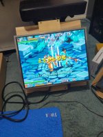
We have video. Its gnarly because its going through one of those Chinese CGA->VGA converters and needs positioning as well as color adjustments, but it is providing video. I figured I could risk my PGM board and not my Martial Masters cart, so I threw a Knights of Valor cart I dont mind losing and it worked just fine. No controls or sound hooked up at the moment, but I can definitely see that the PSU is working properly as is the converter board.

Again, thanks for the help!
For future testings , check this out (will takes you where is great) … its FTW :

https://www.arcade-projects.com/thr...your-recent-purchases-thread.1970/post-303938

✌🏻
 
Also and maybe I am wrong as someone else pointed out, it looks like you have your red positive probe on 5V and your black negative probe on 12V.
This really is not advisable at all if this is what is happening. You are shorting your 12V rail to your 5V rail.

That's not right. You cannot short things with a multimeter when reading voltages as it doesn't load the circuit. Instead you would just be measuring the difference between the two voltages, so the multimeter should show around -7V.
 
Lookin' better.

Colors are still a bit saturated but I believe there is a set of adjustment pots on the board that can modify that.

4a23d4da2e17aab2c178b7d3509fbd2b.0.jpg
 
For future testings , check this out (will takes you where is great) … its FTW :

https://www.arcade-projects.com/thr...your-recent-purchases-thread.1970/post-303938
while a cool little board and a neat piece of history, the lack of audio and Monochrome graphics makes it not a great test board IMO. ok for the initial voltage setting I guess but not much else

A pgm motherboard will boot to a logo and bios menu, without a cart, and that’s enough load for testing next time
Ineed

Personally I use a pandora's box as a test board when trying out new or freshly repaired monitors/psus/cabs... full sound and color, many games for many typtes of test and the best part is if the board gets totally fried it's no love lost to toss it in the trash and buy another one.
 
That's not right. You cannot short things with a multimeter when reading voltages as it doesn't load the circuit. Instead you would just be measuring the difference between the two voltages, so the multimeter should show around -7V.
My mistake that actually makes sense tbh
 
So I hooked up my Primal Rage after getting the PGM going and it worked.

Though one thing concerns me. The PR board has a couple of LEDs, 5.0 Lo and 5.0 Hi. The 'lo' is on so I checked the voltage at the JAMMA edge and it read low, like 4.7 or so. Problem is the PSU is cranked all the way to the high end. Any lower and the board crashes due to too low voltage.

I remember having to crank the PSU for my Blast City in the past to run Primal Rage, so maybe that's the norm for this board? I know it's rather hungry but if it's working, it's working.
 
I checked the voltage at the JAMMA edge and it read low, like 4.7 or so. Problem is the PSU is cranked all the way to the high end. Any lower and the board crashes due to too low voltage.

You'll want to make sure your 5V and GND wires are thick enough (I like 18-16awg for power wires) Also that you have solid crimps on the terminals at either end of the harness.
And of course make sure that the JAMMA Edge and JAMMA connector are both clean (I use liquid DeOxit and a fiberglass pen to clean my JAMMA edges)

if all of that is good then you may want to look into a more powerful PSU
 
Good tips, thank you. I know the JAMMA connector is clean (its brand new) but the PR board could use a teensy bit of cleaning on the contacts. I'll get on that. As far as the wiring, I believe the power wiring is at 18g currently, with the others being smaller (20? I think?). Running the PGM though, the voltage was almost dead on. I've taken everything apart to place it in my garage for a few days until some other parts come in, otherwise I'd have put it together completely. Gonna update my PR project page.
 
Back
Top