Hi, I've got a Nanao MS8-25FTB chassis that has vertical collapse, tube is Toshiba A59JMZ193X, yoke readings (not perfect) are:
0.4 ohm / 0.360mh
6.4 ohm / 25.47mh
While I'm trying to repair the chassis (difficult), could something worse than odd geometry happen if try the tube with a Kortek KTX26 chassis? (game is 15khz)
The usual Zenith monitor yoke readings that work well with Kortek are:
0.7 ohm / 0.750mh
27 ohm / ??
Investigated old threads but couldn't understand if lower impedance could mean risk of burning the yoke or something?
Thanks!
Do not try to use the Kortek chassis, it is made for a standard NTSC yoke (high inductance), where the Nanao uses a high-res yoke (low inductance). The resistance doesn't matter as much as the inductance value, as far as "blowing up my chassis". If you try it, your HOT will fail or worse.
Dead vertical deflection issues are usually pretty easy. If you've done caps, you can look at replacing the vertical IC, looks like an LA7832 in this. Common failure and cheap part to replace.
Got it, I won't try the Kortek then, I guess I'll try it in the future with a TV tube+yoke since you mention it's could be a good fit for standard NTSC yoke (measuring inductance before), but that'll be a different topic, thanks!.
About the MS8-25 vertical collapse issue, this is what I had done with it before bringing it again to the workbench:
Chassis looks in good shape, no signs of anything broken or previous repairs, haven't recapped it yet. Besides the vertical collapse it was shutting down by itself after some seconds - not sure what's the cause of that.
Replaced IC401 LA7832 with LA7833 - arcadepartsandrepair says it's compatible.
Installed socket and replaced IC103 HA11423 just in case (not sure if it could be related)
Measured a bunch of components around the vertical area (ZD401, ZD501, both 6.2v zener are good), and after desoldering and closely measuring 2 transistors that seem related to vertical, multimeter displays some voltage (diode test) between C-E, got replacements, they don't have that weird reading, put them into the chassis but nothing changed:
Q402 PNP 2SA1408 Y - only found an O one to replace it with but hFE looks quite similar, maybe it doesn't even matter.
Q401 NPN 2SC3621 Y
So now I brought the monitor again to the workbench, and this time it doesn't even power on, I hear a slight "psu on" noise, but it is clearly not on, like if it was on shutdown protection or something?, hopefully after recap it'll work again.
Now I was doing a bit more of research since it seems the MS8-29 is quite the same (unlike the MS8-26), and there are an amount of threads about it. Found this one https://www.aussiearcade.com/topic/98425-nanao-ms8-29fsg-no-hv-or-shutting-down/ , mentions the same odd transistors readings that I had, and then his issue was a bad fusible resistor R438, so went and checked mine, it is bad too!, measures megaohms.
The weird thing is that he mentions "It's supposed to be 2.2 Ω", I guess because it's a MS8-29, mine is red/violet/green/green, so 2.7 Ω? (not sure what's the green/green). I'll update once I get to replace it
This is more difficult than expected, I can't find 2.7 Ω 1/2w fusible resistors anywhere, tried mouser/digikey, ebay and arcadepartsandrepair. Also I'm not even sure if it is 1/2w or 1w? measures 8.5mm length, 3mm diameter, so it matches a usual 1/2w carbon but that does not guarantee it.
Also found a parts list but it's from MS8-29, and not complete: https://wiki.arcadeotaku.com/images/2/2e/MS8-29FSG_manual_partlist.pdf
Closest I could find is a 1W 2.7 Ω one, I wonder if it would be safe to use it? it is curious that it is 1W but smaller (6.5mm length) https://mou.sr/4lrf9rc Vishay PR01000102708JA500
Also I don't even know if it's really fusible, only thing it says in its datasheet is "defined fusing characteristics" but not classified as fusible
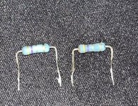
Closest one that is really fusible is 2W 2.7 Ω (10mm length), so it would be clearly above the required wattage, this could mean it could not fuse when needed https://mou.sr/3I4JQnF Vishay PR02FS0202708KR500
Could a fusible resistor be made somehow by combining a regular resistor and a fuse in series?
Replaced R438, with the Vishay PR02FS0202708KR500 2W 2.7 Ω, fits nicely, and recapped it, but nothing changed, it was good to do it anyways, probably fixed other unseen issues, one of the capacitors had 90ohms ESR!
Then I could not make it turn on again, but that was due to me having inserted the HA11235 chip upside down
After reinserting the chip, the vertical collapse was solved. Shortly afterwards found unadjustable heavy red bleed/smearing, pots did adjust the color but not the bleed.
Went to check neck board transistors with a multimeter, the MS8-26 schematic is quite similar, red related components are named 30X, green 31X and blue 32X. One of the small red related transistors gave an odd voltage reading between its legs, sometimes can happen due to a diode being around, etc. so went to check for the same in the blue related transistor, that reading wasn't there. Upon closer inspection, D301 (1SS133) connected to the transistor looked suspicious, had a 1.8v forward voltage reading, while other diodes have 0.6v. Took it out, checked that still was the same off-circuit, and also it had a frosted glass look. Replaced it with a 1N4148, turned the monitor back on, issue solved
I wonder what's the appropriate B+ for this chassis? only know that MS8-26 is 92v and MS8-29 is 94v. Kept it at 92v just in case
Here is the cap list of all the original capacitors the chassis had minus the filter:
The monitor was running alright, but after 5-10 minutes red color would begin to flicker, sometimes went full out, and sometimes went normal back again for a while, quite weird, very unstable.
So began by checking:
Connection from board to monitor, tried something different (TPG) - no change
Gain/bias pots - no change
Took the monitor to the workbench, I suspected the issue would be at the neckboard but wanted to be sure, so using the cheapo battery powered scope measured the red color and black (gnd) wires that go to the neck board:
Having a crosshatch pattern on screen I could see certain "square" wave, because red had always the same intensity. When the flicker issue began to happen and then red was out, the wave did not change at all. I think if the issue was on the mainboard (circuit previous to neckboard) that wave should have changed in some way too, so that confirmed I should really check the neckboard.
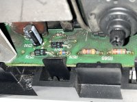
Measured around the red related components, found a voltage difference when measuring in circuit in reverse D302 (red) vs D312 (green), later I found it wasn't the diode, a resistor R306 (100 ohm, fusible) was open.
Replaced it with a regular 1/4w one (may later get a fusible one), I think the worst that could happen would be it burning to a crisp.
So took out the only zener from the neck board: ZD301 15v.
Tested out its zener voltage with a bench supply, all good, that had me puzzled, but decided to try and put a new one there just in case (a bit larger but same).
That fixed the issue! - had it on for 3 hours now, not a single flicker
This monitor was working nicely, until a couple of weeks ago all of a sudden no longer displays an image , just displays black, as if it was off, but it is up and running, just doesn't pick up the input video signal.
Turning the screen pot causes it to display raster, so we have a screen.
Tried with a TPG to discard game board issues, same result. It can be seen how the raster changes frequency with the input signal on/off, so it is taking the video sync, but no image at all, not even turning on the brightness or colors.
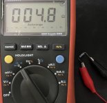
I've seen in other posts that some 4.7ohm fusible resistors near the flyback could be causing this issue, but I measured them and they're good.
I wonder where to go from here, what else to check?, any advice appreciated!
This monitor was working nicely, until a couple of weeks ago all of a sudden no longer displays an image , just displays black, as if it was off, but it is up and running, just doesn't pick up the input video signal.
Turning the screen pot causes it to display raster, so we have a screen.
Tried with a TPG to discard game board issues, same result. It can be seen how the raster changes frequency with the input signal on/off, so it is taking the video sync, but no image at all, not even turning on the brightness or colors.
I've seen in other posts that some 4.7ohm fusible resistors near the flyback could be causing this issue, but I measured them and they're good.
I wonder where to go from here, what else to check?, any advice appreciated!
Thanks @cruzlink2 , I have already taken R570 and R572 out too just in case and they are both alright
Now that you mention "Video B+" I guess I'll try measure its path to really see if it's arriving to the neck board
Thanks @cruzlink2 , I have already taken R570 and R572 out too just in case and they are both alright
Now that you mention "Video B+" I guess I'll try measure its path to really see if it's arriving to the neck board
Red color is reaching the neck board, this confirms color amplification has to be working. Also the Red Gain / Bias shape the signal as expected (gain makes it taller, bias changes its offset), so color processing at the main board is fine
Could the issue be related to Brightness / ABL?
I checked the brightness wire going to the neck board, and it has around 11v.
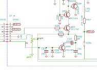
Then I saw at the MS8-26 service manual, that at Q572 base there should be a wave going from 3 to 11v, measured that:
And it's pretty much the same as the brightness output, it is at 11v with that tiny periodic bump, so could this be the issue, could I be getting closer? not sure.
Measured out of circuit the transistors from the docs Q570 Q571 Q572, they all checked good. D574 too.
Tried a weird idea, if the brightness voltage is stuck at 11v and should be lower to display an image, what about if I bring it there myself?
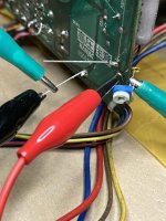
Disconnected brightness wire from neck board, attached it to a 2K pot, attached the other end of the pot to GND so it could act as a "voltage divider". Turned it and brought the voltage to around 7v:
This confirms that I really have an issue with the ABL / brightness control..
When the monitor used to work sometimes when powered on it was unable to lock sync so the image would slowly roll over for a while, but now the V.Hold pot does only change how fast does it roll or to which direction, but the image never locks in, weird, other issue to figure out. What could it be?
I had reflown the most important parts (connectors, pots, hot, crt pins, fb pins..), but now that you mention, yes, it's a good idea to reflow everything so just did that, all joints, including the not a remote pots pcb, and nothing changed - I still have no video, and if I do the brightness wire hack I've got no v-hold too
Thanks, even if PNL is far away, for a very tough expensive chassis it could be worth it.
About Uruguay, I haven't found any expert, I guess there should be at least one that does maintenance for the few publicly available CRT cabinets that remain around, but anyways they're steadily being replaced with mostly chinese clone cabs, VR, kiddie rides, redemption, etc. Anyways I have to keep on trying my best, because I've got plenty to fix, and what's fixed now might break sooner or later..
Got an update about this, it is fixed!. The cause of both (no video and no V.Hold) issues was IC102! - which exact part of it I don't know yet.
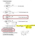
I was tired of trying to find the cause of the no video/brightness issue, so began to check the rolling image issue, the MS8-26 manual says if you have a vertical sync problem: check IC102 "PCB SYNC", PC501 and their related components.
Checked the related components and didn't found anything, before digging into IC102 I wanted to know more about it beyond the schematics and remembered I had once downloaded a PDF in german language that described the operation of the different Nanao IC PCBs in extensive detail https://files.arcadeinfo.de/Winnis Reparaturanleitungen/Nanao-MS8-xx-Custom-PCBsRev1.1.pdf
I was translating it piece by piece when I found something very interesting:
I had a short circuit in the Q2 here... with the result that the picture remained completely dark... permanent “blanking”!!
So this is proof that IC102 could also cause "no-video" issue, that's all the motivation I needed to go remove and check it.
Now reviewing this again I notice that if I had checked PC501 first, I would probably have found that it was not having a vertical input signal, and that should be the cause of the inability to lock V.Hold, but now its too late to check..
Checked IC102, didn't found much, some transistor diode values were odd but probably because of resistors connecting different transistor pins and stuff.
Got a MS8-26 untested chassis nearby that shares the same PCBs, so took the plunge and removed its IC102, installed it on this one and turned it on. Both issues were solved
I'll be examining the IC102 pcb, going to need it sometime..
Thanks, even if PNL is far away, for a very tough expensive chassis it could be worth it.
About Uruguay, I haven't found any expert, I guess there should be at least one that does maintenance for the few publicly available CRT cabinets that remain around, but anyways they're steadily being replaced with mostly chinese clone cabs, VR, kiddie rides, redemption, etc. Anyways I have to keep on trying my best, because I've got plenty to fix, and what's fixed now might break sooner or later..
Got an update about this, it is fixed!. The cause of both (no video and no V.Hold) issues was IC102! - which exact part of it I don't know yet.
I was tired of trying to find the cause of the no video/brightness issue, so began to check the rolling image issue, the MS8-26 manual says if you have a vertical sync problem: check IC102 "PCB SYNC", PC501 and their related components.
Checked the related components and didn't found anything, before digging into IC102 I wanted to know more about it beyond the schematics and remembered I had once downloaded a PDF in german language that described the operation of the different Nanao IC PCBs in extensive detail https://files.arcadeinfo.de/Winnis Reparaturanleitungen/Nanao-MS8-xx-Custom-PCBsRev1.1.pdf
I was translating it piece by piece when I found something very interesting:
So this is proof that IC102 could also cause "no-video" issue, that's all the motivation I needed to go remove and check it.
Now reviewing this again I notice that if I had checked PC501 first, I would probably have found that it was not having a vertical input signal, and that should be the cause of the inability to lock V.Hold, but now its too late to check..
Checked IC102, didn't found much, some transistor diode values were odd but probably because of resistors connecting different transistor pins and stuff.
Got a MS8-26 untested chassis nearby that shares the same PCBs, so took the plunge and removed its IC102, installed it on this one and turned it on. Both issues were solved
I'll be examining the IC102 pcb, going to need it sometime..


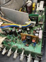
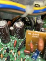
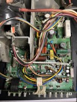
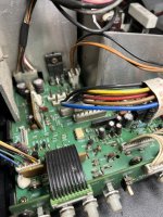
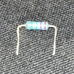


 - how did the monitor work with it open? not sure.
 , just displays black, as if it was off, but it is up and running, just doesn't pick up the input video signal.