What's new

atomiswave16

Beginner
Joined
Aug 5, 2020
Messages
3
Reaction score
1
Location
california
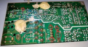
I was taking pictures of my Nanao M8 29FSG monitor chassis to familiarize myself of the board before I begin re-caping it when I noticed that there are missing solder on these points and was hoping there is someone here who is more familiar with these would know if this is normal or not.

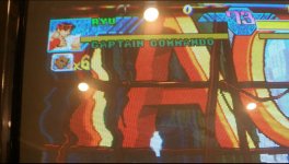
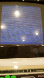
But could this be the reason the image on my monitor started degrading and ultimately failing last year? It started with the picture having wavy edges which then progressed to the image scaling down and not seeing anything but wavy lines

Thanks for any help
 

Attachments

  • Missing Solder Possible._01.jpg
    Missing Solder Possible._01.jpg
    209.1 KB · Views: 95
  • MonitorWavy_01.jpg
    MonitorWavy_01.jpg
    167.3 KB · Views: 96
  • MonitorWavy_02.jpg
    MonitorWavy_02.jpg
    200.2 KB · Views: 83
  • MonitorFailure.jpg
    MonitorFailure.jpg
    79.1 KB · Views: 93
it looks like there's no pad or trace there to solder to. Must be no-connection by default.

I think the new caps will actually fix those wavy geometry issues. The last image though I can't say. That one is really screwy. It completely loses picture, it's not just out of sync or hold. The image looks like snow or random? Hopefully the caps fix it, but there could be something else wrong... maybe something on the RGB input or on the neckboard.
 
Those pins on that transformer aren't used, so no missing solder there and no pads/traces to connect them.

As has been said, if you or someone else hasn't already, definitely recap that chassis.

Check and make sure your dag wire is connected from the CRT to the neckboard, otherwise that can cause wavy-ness/ground interference.

Lastly, check your adjustment pots, specifically the H and V Hold pots--turn the monitor off, remove the remote board, make note of their current positions and spray them with some deoxit and turn them left/right a few times to work it through. Maybe check the solder joints for them as well, and lastly measure resistance on them (V Hold should measure about 5k Ohms, H Hold about 3k Ohms).
 
Wow, thanks everyone for all the info and am glad to know there wasn't anything that popped off the board. I will try all of the suggestion and hopefully it will fix my display issues. I do have one more question, how to remove what looks like 2 dollops of glue from the board? It looks like it will cause some difficulties when I start re-capping.
 
u can just carefully peel it off with your finger or a small plastic scraper. dont scratch the board tho
 
Wow, thanks everyone for all the info and am glad to know there wasn't anything that popped off the PCB. I will try all of the suggestion and hopefully it will fix my display issues. I do have one more question, how to remove what looks like 2 dollops of glue from the board? It looks like it will cause some difficulties when I start re-capping.
isopropyl alcohol. 99% preferably, but 90-91% should also be fine. 70% is not ideal but will work.
 
Back
Top