The other thread is getting long, and I'd thought I should write a quick summary of what's involved.
First off, it's very doable - BUT, you will need some gear to do it.
1 - Fancy programmer with TSOP44 adapter
27C322 eprom for IC22
MX26L6420MC-90 flash for the rest. I got mine off ali-express, I paid 30USD shipped for 20 pieces that came in tape and looked all new - but had some Sanyo stuff on them. Probably some factory-programmed left-over stock.
I had a couple of the TSOP44 adapters, one worked OK - the other one not so well. In general it seems the smaller pitched adapters have issues with making good contact with all pins at the same time.
2 - Hot air station, or other means of removing large SMD IC's
3 - Good soldering iron, flux, isopropyl etc etc
4 - I don't do SMD work without magnification (microscope) anymore, and kick myself for not getting magnification earlier. It's not a matter of what's possible, with magnification you take a lot of luck out of the equation.
Moving on..

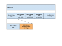
This is the general idea, kindly provided by Metallic. You need cleartext GD-ROM image, preferably non-patched for net-booting.
1* - Write the first 4MB to a 27C322 eprom. The second half of the first 8MB chunk SHOULD be empty, as it's not mapped to cart memory. In the case of Ikaruga, there IS data in the second half - more on this later.
2 - Write the second 8MB chunk to IC1, third to IC2 etc as in the diagram above. I use a Wellon VP-490 programmer, and it has a nice feature that lets you specify offset of input file - offsets in diagram above. No interleaving or other funny business.
Ikaruga game file is 33,554,432 bytes long, which is exactly 5 8MB chunks. The last one (IC4) is all 0xFF, so no need to install it.
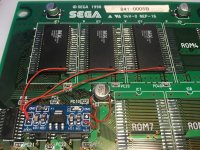
The naomi cartridges use 5V, and the MX26L6420MC is NOT rated for 5V, and data-sheet makes no claims or indications that it does, but it seems to work. How long it will work is another issue. As the other thread showd that others had used some diodes and resistors to knock down the voltage, I used a small 1117 based regulator board to provide clean 3.3V for it. To feed the IC 3.3V, you need to lift the VCC pin and solder a kynar wire to it. This is kludgy.

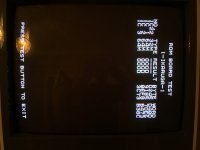
And that's basically it. With only IC22 in place, test menu should show which game it is.
Now - there are a couple of gotchas..
For the first point, rtw did in record speed relocate the game test part of Ikaruga to the first half of the first 8MB chunk, so that works. He also patched so that ROM test works. Also very impressive was that this was done 'blind' without testing, and it worked on the first try! This is in other words a clean IC22 that not a copy of the work done by arcademodbios.com.

So there you have it. I didn't really do much other than the 'plumbing' and write-up on this one, so credit due to the persons mentioned above and all the good info from you guys in the other thread.
PS: please don't use this info to sodomize perfectly fine working carts with a Weller iron to sell it on ebay..
First off, it's very doable - BUT, you will need some gear to do it.
1 - Fancy programmer with TSOP44 adapter
27C322 eprom for IC22
MX26L6420MC-90 flash for the rest. I got mine off ali-express, I paid 30USD shipped for 20 pieces that came in tape and looked all new - but had some Sanyo stuff on them. Probably some factory-programmed left-over stock.
I had a couple of the TSOP44 adapters, one worked OK - the other one not so well. In general it seems the smaller pitched adapters have issues with making good contact with all pins at the same time.
2 - Hot air station, or other means of removing large SMD IC's
3 - Good soldering iron, flux, isopropyl etc etc
4 - I don't do SMD work without magnification (microscope) anymore, and kick myself for not getting magnification earlier. It's not a matter of what's possible, with magnification you take a lot of luck out of the equation.
Moving on..

This is the general idea, kindly provided by Metallic. You need cleartext GD-ROM image, preferably non-patched for net-booting.
1* - Write the first 4MB to a 27C322 eprom. The second half of the first 8MB chunk SHOULD be empty, as it's not mapped to cart memory. In the case of Ikaruga, there IS data in the second half - more on this later.
2 - Write the second 8MB chunk to IC1, third to IC2 etc as in the diagram above. I use a Wellon VP-490 programmer, and it has a nice feature that lets you specify offset of input file - offsets in diagram above. No interleaving or other funny business.
Ikaruga game file is 33,554,432 bytes long, which is exactly 5 8MB chunks. The last one (IC4) is all 0xFF, so no need to install it.
The naomi cartridges use 5V, and the MX26L6420MC is NOT rated for 5V, and data-sheet makes no claims or indications that it does, but it seems to work. How long it will work is another issue. As the other thread showd that others had used some diodes and resistors to knock down the voltage, I used a small 1117 based regulator board to provide clean 3.3V for it. To feed the IC 3.3V, you need to lift the VCC pin and solder a kynar wire to it. This is kludgy.

And that's basically it. With only IC22 in place, test menu should show which game it is.
Now - there are a couple of gotchas..
- ROM test will not work, as the GD Image has no idea that it now lives on a cart and has no information on size or checksums of the eproms, also for Ikaruga, there IS data in the second half of the first 8MB chunk. This is the game-test code, so that will not work as it's not written to the cart.
- Naomi DIMM memory is mirrored, meaning the same data is available on two different addresses, which is not the case on a cart. If the GD-ROM game happen to use the wrong address, patching needs to be done - luckily this is not the case for Ikaruga. This info was kindly provided by Metallic.
For the first point, rtw did in record speed relocate the game test part of Ikaruga to the first half of the first 8MB chunk, so that works. He also patched so that ROM test works. Also very impressive was that this was done 'blind' without testing, and it worked on the first try!
 This is in other words a clean IC22 that not a copy of the work done by arcademodbios.com.
So there you have it. I didn't really do much other than the 'plumbing' and write-up on this one, so credit due to the persons mentioned above and all the good info from you guys in the other thread.
PS: please don't use this info to sodomize perfectly fine working carts with a Weller iron to sell it on ebay..
Last edited:

