What's new
I know the CPU itself is good as swapping out/in the other good one still has the same effect - so its something as you mentioned, outside of hte 6809. I will check the other data lines tonight and see what I see. Thanks for all the hints/tips!

Matt
 
@mathewbeall always glad to help someone who is willing to work for their boards. Good luck!

P.S.: don't forget the Fujitsu 245! Fujitsu TTL chips are... crap. Yes, that's the technical term.
 
Ok - making more headway. For pins 8-31 on my working board, all are blinking with the logic probe. On the board not working - pin 20 and 22 (on the sound CPU) are stuck high.

Pin 20 - SNA12
Pin 22 - SNA14

It looks (in the diagram) that these are going to CUS30 (socketed at H3). I just tried swapping H3 on the boards, but that didn't fix the issue.

It seems as if SNA12 and SNA14 originate in CUS30? I can't really see where they might come from - even though the diagram shows SNA0-15 going to a different page.

1618974526402.png


Edit: More information

on the demo sequence

1618977505696.png


What I can't quite tell is where the signals originate from (ie - the source of the problem).
 
Last edited:
Good sleuthing. Let's step through it:

"SNA" in this case is Sound CPU Address Bus (as opposed to SND which is Sound CPU Data Bus). The bus is shared by several devices:
- Sound CPU (schematics page 6)
- Custom 30 (sound control custom) (schematics page 6)
- HM6264 sound RAM chip (schematics page 6)
- Custom 121 (sound CPU address decoder) (schematics page 6)
- Two LS257 TTL chips located at P3 and N3 (schematics page 6)
- Three LS257 TTL chips located at K1, L1 and M1 (upper-left corner of Page 7)
- J1 DIN connector that connects to the ROM board (Page 8 ).

Fortunately it's only SNA lines 12 and 14 that appear to be culprits - that narrows our scope a bit. You were wondering what the "source" is for the signals. The answer is the Sound CPU - it sets the address lines for whichever EPROM or RAM addresses it wants to read in, as well as the addresses it wants to write data out to. Customs 30 and 121 work with it to make sure data from the correct sources flow in, and processed data goes out to the appropriate destination. The customs are also "black boxes" in that there isn't any formal documentation for them, although we can deduce some of their behavior from the schematics. There's also some TTL chips that manage some address & data line communications to a memory chip located at H1 that is shared between the main/sub CPUs and the sound system. We're getting into complex territory here unfortunately.

Let's keep it simple for now by verifying continuity on the suspect lines between all the components that use them. A damaged trace is far preferable to a failed Custom. Fortunately we can rule out Custom 30 as a culprit since you cross-checked it with your other board. Let's focus on SNA12 first.

- Check continuity for the J1 pin connector - it's responsible for feeding data from the ROM chips on the game board into the CPU board. SNA12 is Pin A40 on the connector, although SNA14 is not connected. Your multimeter should read continuity between J1 Pin A40 and Sound CPU Pin 20. Also detach the ROM board and make sure there isn't a missing or bent pin inside the connector. SNA12 runs through the connector J1 over to the two sound ROMs in the lower-right corner of the ROM board located at A10 and B10, on Pin 23 of each chip (page 8 of the schematics).

- SNA12 also connects between the Sound CPU, HM6264 sound RAM at location U3, Custom 121, and Custom 30. Verify continuity on the SNA12 line between each of these components.

- As best as I can tell, SNA14 is only used between the Sound CPU and Custom 121 - I'm not finding it anywhere else on the schematic. Verify continuity on that line between those components.

There's a lot more we can test, but let's keep the focus narrow and check these first. Fingers crossed you find a broken trace somewhere in the SNA12 chain!
 
Last edited:
Ok - finally got some time this morning to do more testing!

Sound CPU pin 20 has continuity to J101 connector, pin 40. Looked at the 3 connectors - they look fine, no bent pins.

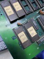
Over to the EEPROMS - from the schematics I see - SNA12 goes to pin4 on the sockets - correct? Which interestingly enough, is pin 2 on the chip? Is it possible these EEPROM's aren't seated in the right pins?. There are many on this board that aren't the same size, and they start 2 or 3 down. Here is a picture of the sound EEPROMS.
 

Attachments

  • IMG-3448.jpg
    IMG-3448.jpg
    237.9 KB · Views: 103
Continuity for SNA12 seems good to all points it touches.

Continuity for SNA14 seems good - it actually not only hits CUS121 on pin 55 but also CUS30 (h3) on pin 10 (through a LS04 diode at p4). With no power to the board, I have continuity from Sound CPU pin 22 to LS04 (p4) pin 11.
 
Ok - finally got some time this morning to do more testing!

Sound CPU pin 20 has continuity to J101 connector, pin 40. Looked at the 3 connectors - they look fine, no bent pins.

Over to the EEPROMS - from the schematics I see - SNA12 goes to pin4 on the sockets - correct? Which interestingly enough, is pin 2 on the chip? Is it possible these EEPROM's aren't seated in the right pins?. There are many on this board that aren't the same size, and they start 2 or 3 down. Here is a picture of the sound EEPROMS.

Those EPROMS are in the right place, System 1 games can have a mix of 64kbyte (28 pins) and 128kbyte (32pins) EPROMS, all sockets on the board support 128kbyte EPROMS, maybe pacmania uses 2 x 64kb instead of 1 x 128kb because it was cheaper at that time?, Tank Force uses just one 128kb

left: my pacmania, right: tank force
pacman.png
tankforce.png
 
Since continuity is OK I would try and replace the RAM (HM6264). RAM is usually a weak spot on many boards, i.e. prone to failure.

I think it's socketed so you can just use one from your good board if that's the case.
 
Actually - the initial error was "SOUND RAM2 ERROR" - and I did replace the U3 RAM. It wasn't socketed, but wasn't hard to replace.

Are you suggesting I replace the other RAM chip as well (U2)?

Matt
 
Actually - the initial error was "SOUND RAM2 ERROR" - and I did replace the U3 RAM. It wasn't socketed, but wasn't hard to replace.

Are you suggesting I replace the other RAM chip as well (U2)?

Matt
Both U2 and U3 are right there at the "sound generator" part of the pacmania schematic, don't know which one would be "RAM2",.. but if replacing one doesn't work I'd replace the other. And I had a pic I took from my pacmania board where you can see the 6264 exact model, maybe you find it useful, good luck!
I suggest replacing U2, since also, the link you had posted at the beginning says
Symptom: Sounds f/x present but no music (CPU Board fault)
Cure: No address lines active on the 6264 RAM at location U2, data lines all dead. Cure: Bad 6264 RAM at location U2 (not reported in test mode) – replaced bad RAM, so fixing the fault
Sound RAM2 Error -
Sound RAM3 Error - 6264 at location U3
So RAM2 Error should be U2 I guess.
At the moment, which sounds is the board emitting? music or samples?
 
Well - right now, if I boot up outside of test mode - it goes to the main screen with no sound on the demo screen, and then I insert a coin, and press start - I select a level (all with no sound) and then when the next screen occurs - with pacman going from left to right - I hear applause - so that I am sure is a sample. However, at this point - I can't move on to the next screen (to play the game). This did work before I replaced U3.

So I would say (currently) no music or sound effects, just samples - as the sound CPU is "non functional".

@MagicianLord77 - I will replace U2 - no reason why not!

Matt
 
Edit: removed incorrect explanation for why replacing the RAM at U2 could work.

@mathewbeall I'm sorry, I forgot you had already replaced one of the RAMs.
Yes, I mean the one at U2.

I happen to be in the middle of organising my PCBs and have Pacmania at hand. I'll take a look at it and see if I can remember anything else.
 
Last edited:
Ok, the fact that it's the music that is missing is a major clue that the issue is on the YM2151 side of the sound generation circuit. If you look at the schematics you can see that the CUS121 is connected to the U2 RAM and the YM2151. Both of these are isolated from the sound CPU and can only be accessed through the CUS121.
If you check the data and address lines of the U2 RAM it's likely you'll find something amiss.
Since the RAM shares its data bus with the YM2151 you may also try replacing the latter if replacing the former doesn't work.
Can you tell I've had my coffee now? :D
 
Ok - I already have a chip for U2 coming, and I just purchased a YM2151 - I will replace the RAM first, then the YM chip and see how things look.

Matt
 
@mathewbeall if you can, try to probe the RAM now and after you remove the YM2151... I think you may find something interesting.
Also, at this point does the RAM error clear? What about after you remove the YM2151?
 
The RAM error cleared after I replaced U3 a while ago, and the error then became "SOUND CPU NOT RUNNING".

Next step will be the YM2151.
 
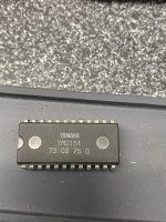
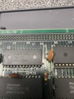
I got the Ym2151 late (today) but just soldered the new one in. I have a feeling its slightly different somehow - since when I boot the game I get garbled static basically. And when I go into the test mode I still get "SOUND CPU NOT STARTED". I will likely solder the old one back in. The picture of the one on the board is the NEW one.
 

Attachments

  • IMG-3479.jpg
    IMG-3479.jpg
    214.6 KB · Views: 90
  • IMG-3478.jpg
    IMG-3478.jpg
    161.2 KB · Views: 98
I put the old YM2151 back in, and it is back to "normal" which is to mean the sound CPU is not running.

If anyone has experience with these boards, or just more experience than I have - and is willing to do some troubleshooting for hire - send me a DM. I have hit my limit I think on what I can figure out.

Matt
 
Did you replace the 74LS04 at P4? The one connected to SNA14?
 
Back
Top