What's new

hatmoose

Champion
Joined
Mar 25, 2021
Messages
1,089
Reaction score
2,269
Location
New Zealand
This one came to me as "parts or repair only" and had been repaired unsuccessfully by someone else. Normally this is a bad sign - nothing harder than undoing someone elses failed repairwork before repairing

But I gave it a go anyway

Monitor Was dead, dead - would not power on because power switch was stuck - suspect stuck power switch

Disassembled chassis, repaired impact damage, straightened chassis, re-glued all mounting posts with the local equivelent of JBweld plasticweld epoxy putty, freed up stuck power switch, confirmed correct operation of power switch, re-assembled

Switched on power with working power switch - monitor would not power on - no green power light, no degauss sound, no neck glow, no static electricity on tube - suspect bad power supply

Measured voltage at power supply - input voltage OK, no output voltage on any line - suspect dead power supply.

Inspected power supply - previous owner had attempted (unsuccessful) repair. Weirdly enough they had not swapped the big power transistors or the big caps that normally cause them to fail. But it was a bloody mess. Gave up trying to fix someone elses failure.

Swapped dead power supply with known good power supply from 1995 PVM-14M2

power on to pulsing green power light, no degauss sound, no neck glow - suspect bad HOT (2SD1878-CA at Q501)

Remove HOT, Test for short across HOT emitter pad and ground, no short. Test HOT, HOT Bad

Replace HOT with known good HOT (2SD1878-CA at Q501) borrowed from another monitor

power on to solid green power light, degaus sound, neckboard glow, static electricity on tube, no picture - suspect Power supply voltage.

Measure power supply voltage output +115 good, -15 and +15 too low. This was interesting because this same power supply functions perfectly in a 14M2.

Replace power supply with another known good power supply one from a year 2000 14M2

Power on, working as expected, fixed


Other notes: IIt's unusual for the power supply to be dead-dead, normally they will produce something on some line, but not in this case. I'm not sure if it failed like this, or if the incompetent attentions of the previous owner left it in this state
So I'm unsure if the power supply popped and took out the HOT, or of the HOT went and took out the power supply. Normally the power supply goes first and destroys the HOT.

The HOT is an NPN transistor with diodes and clamp resistors and all other kinds of weird stuff. It's hard to get sensible test results with a multimeter.

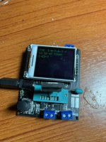
In my transistor tester the known good one looked like 2 diodes
IMG_0067 (1).jpeg
the bad one would not even test, For some reason it kept forcing the tester into self test mode.
 
nice work! i was able to fix a commodore 1084p monitor once by changing the NPN too (used the same china tester as well) ! its very satisfying to repair an old CRT i must say.

your workbench must have looked great while you were operating - PVM's opened up and all over the place ? :cat:
 
nice work! i was able to fix a commodore 1084p monitor once by changing the NPN too (used the same china tester as well) ! its very satisfying to repair an old CRT i must say.

your workbench must have looked great while you were operating - PVM's opened up and all over the place ? :cat:

Those transistor testers are awesome aye? I think that one cost me twenty bucks maybe - the battery is worth more than the device. I dont know if there is a manual or anything but if you have one I'd love a link :)

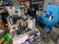
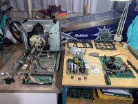
Picture of the pigsty for your viewing pleasure - I'm between jobs at the moment so I have tonnes of time, but I can only buy cheap stuff for repair - so I have a lot of stuff that needs repair :)
IMG_0116.jpeg
 
great photo thanks a lot for providing this :thumbsup: good luck with the rest of the monitors !
here is a link to a rather verbose manual

i had another manual but cannot find it right now, i just googled this one from a quick ali express search for "lcr-t4", well i started out searching for "npn tester"
 
For practise I swapped the broken tube from the BVM 20E1E that I'm working on into this PVM 20M4.

there is sometimes confusion about the difference between the "splotchy" colour purity issues from a shifted yoke, and the "rainbow" from a damaged Aperture Grille

This is what a damaged Aperture Grille looks like

Swapping tubes for Lulz is not recomended - the tube is tuned to the yoke at the factory - if you need to change yokes when you swap tubes (like I did here) it is a lot of work to re-tune the tube to the new yoke.
 
Eventually I will get around to repairing the power supply from this monitor, when I do this will come in handy, copypasta from another forum

Faults like this that cause chain– reactions of destruction are demoralising, especially when they destroy devices like this repeatedly!

Begin with the power supply:–
Note there is no high–capacitance mains h.t. smoothing in this design, three 0.47 μ 630 V capacitors in parallel, C612, C613 and C638 are all that is used in this design!
Replace the two resistors R1602 and R1603 from the mains h.t.+ line to the source pin of the STR–M6524, the device will be repeatedly destroyed if either of these go high or o/c!
Next replace the following electrolytics in the power supply:–
C616, C618 and C619 and also make sure none of the secondary side reservoir capacitors C621/3/5/7 & C629 have gone rotten, replacing as necessary!
Next check the primary side snubber components for dry joints/open circuits :–
R603, R627 and R630 – these run very hot in service, the snubber capacitors C614 and C635 for open–circuits or dry joints, and the primary side flyback tuning capacitor C615 for open–circuits or dry–joints.
The opto–coupler PH601 (Sharp PC111) will also destroy IC601 if it goes too low emission – the LED does – replace this with a new one!
Finally make sure you're not using a really cheap STR–etc., ICs, some of these have been faked, and also remove the power supply transformer T603 from the PCB and resolder the wire ends where they connect to the pins!
The h.t. controller IC602 has no components associated with it likely to cause repeated failure, a short on the h.t. output line, which I will come to next, is the main thing that destroys this IC!

Line–scan oscillator stage:–

Replace C531, C537, C541, C549, C550 and C552, these are all critical for correct drive and stability of the oscillator combination IC, the μPC1377 IC502!
Make sure the timing components C538/C539 and R553 are all the correct values also!

Line Driver stage:–

Replace C529, check R520, R532 and R543 (Fusible resistors sometimes go high in value) and resolder the wire ends of the Line Driver Transformer T500 where they connect to the pins. S/C turns in these aren't very common but Ed Dinning may be able to help if you suspect this!

Line Output Stage:–

The first thing I was thinking about when I read your tale was a "fake" or poor quality Line Output Transistor, try one from another supplier to what you previously used if possible!

Make sure the flyback tuning capacitors (C525, C526 & C527 in parallel) are all ok and not dry jointed, and make absolutely CERTAIN there are no burn–ups/dry joints in the scan coil plug/socket and the associated wiring, and also at the scan coils connection board itself!

Sony line flyback transformers are fairly reliable and in the years that I worked on monitors I never had to replace one!

Finally it is worth replacing the two electrolytic capacitors C523 & C592 associated with the beam–current limiter protection IC, IC500!

There's a great deal to go through I admit, but with a monitor as complex as this one is, you can't afford to take short cuts or miss things, this is why I've written it out in so much detail!

One of those little Chinese colour screen LCR–T1 Component Testers (about £20), etc., will be adequate for checking out all the non–electrolytic timing or tuning capacitors I enumerated above!

Finally make sure the h.t. voltage and over–voltage protection adjustments as detailed in the s.m. are accurately carried out as directed in the book once you've got it working!
 
That's my thread so if you beat me to it, let me know.

FWIW I've been through his checklist and the only anomily I've found were R1602 AND R1603 reading slightly low in and out of circuit. I'll be replacing the caps noted (most have already been done) but I've a feeling it's something else on that power board or fake components. Since these aren't available new anymore, it's pretty much a crap shoot.
 
Last edited:
That's my thread so if you beat me to it, let me know.

FWIW I've been through his checklist and the only anomily I've found were R1602 AND R1603 reading slightly low in and out of circuit. I'll be replacing the caps noted (most have already been done) but I've a feeling it's something else on that power board or fake components. Since these aren't available new anymore, it's pretty much a crap shoot.
I also just posted in that thread regarding my M4U (US variant).
Was trying to clarify if the US model can take a 240V input since the schematic and parts listing is the same for all models even though the service manual description at the start says 120VAC only for the M4U. Someone also just posted up the commercial brochure which goes on to say the US model is also multi-voltage.

Having checked my actual PSU all the parts are as per the schematic but it appears to be triggering some overvoltage protection using 240VAC, it initially powers up generating the right voltages but then proceeds to shutdown, needs more looking into.

For reference there is another thread here @Ikeda that may be worth a look
https://stardot.org.uk/forums/viewtopic.php?t=15930
 
Extreme thread necrobump.

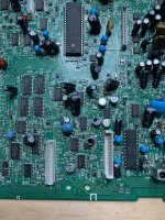
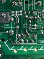
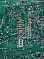
A friend of a friend was cleaning out his storage the other day and had this 20M4 that had been waiting for repair for several years. It truly was in a sorry state when it arrived, a box-o-bits. It had also had a series of other repair attempts from several other folks, repairing a repair can be quite tricky.

I spent about 8 hours working on it, exhausted my supply of spare voltage regulators and HOT's, and eventually reluctantly admitted that it was beyond economical repair.
IMG_4189.jpegIMG_4184.jpegIMG_4186.jpegIMG_4192.jpegIMG_4195.jpegIMG_4197.jpeg

So I contacted the original owner, explained the situation and offered to re-assemble and send back. They said that if I thought it was beyond saving it probably was in fact beyond saving, and sold it to me for spare parts. So now I have another 20M4 with a bad mainboard, a bad power supply and a bad habit of exploding hard-to-find power regulators :)
 
Came back to this one after a long hiatus. I realised that I had a good 20M4 with a bad tube, and a bad 20M4 with a good tube. Should have made this connection earlier.

Anyway, clearly the sensible thing was to transfer the guts of one into the shell of the other leaving me with one fully working 20M4 and one perfectly broken 20M4.

So did all that, and annoyingly was greeted with the red tally light of death.

Chassis would power on (good), green light on(good), power supply chirp (good)
no degauss coil (bad), no static (bad), no neck glow (bad), no picture (bad)
tally light = red

This is classic blown HOT symptoms, but I'd just fixed that on this board - not impossible for them to fail again, but not likely.

Probed G-board (power supply) voltages - two different power supplies gave pretty much the same readings. Did you know that there are at least 3 different M series power supplies? I wish I didn't....

With load (CN605)
+5 = +4.7
+15 = 18
-15 = -16
+115 = +147.5

With no load (CN605)
+5 = +5
+15 = +17
-15 = -16
+115 = +150

Tried both power supplies in a 14M2 - both worked fine, G board OK, Suspect A board.
Realise it's bloody freezing in the workshop, vaguely recall another quick "return to service" trick from the Randy Fromm monitor repair series one million years ago
Hit the A board with the hairdryer for a few minutes to warm it up, return to normal operation.

So definitely a bad cap, not the HOT, but showing classic "bad HOT" symptoms
If I had to guess I'm guessing C529 which does Horizontal oscillation, no horizontal ossolicaiton = no HV, no HV = no flyback, no flyback = no degauss/static/glow/picture

C529 is on the short list of "must change" caps anyway, so I'll get them ordered up.
 
Back
Top