A loooong while ago, circa 2013, I started to convert some Sega Love and Berry and Dinoking cabs. I had to put the project on hold for a few years for various reasons but I'm really happy to say I've just started to get back to work on them ")
I figured they deserved a place here so I'm going to copy a lot of my old posts over if they're of interest and/or of use to any one. I'm going to post a load of information over in one go and I may need to tidy it up a little later so I apologise if some of it is nonsensical. I also apologise for the tiny photos. I used to have a tiny 10" notebook and the photos looked a decent size on there at the time. I'll make sure I post some larger photos for future progress.
All my photos, like thousands of other peoples, were hosted on Photobucket and they no longer show up after they stopped 3rd party hosting on free accounts. I had started to move away from Photofuckit anyway as it was a bit of a shitty service and so there was no way I was going to pay for a premium account. Since then I managed to download all of my Photobucket albums in one go ( using [this] Chrome plugin ) and I've just trawled back through the my posts and updated all of the IMG links. That was fun
Anyway, here we go:
---------------------------------------------------------------------------------- --------------------------------------------------------------------------------- ---------------------------------------------------------------------------------
I've created this thread to document converting two mini Sega cabs I have.
One of them is a Sega Love and Berry cab and the other is a Dinosaur King. There is a wiki entry for them [here]. I'll let you read the information there rather then regurgitate it here.
These are the two cabinets I have:

Here's a photo of my sexy self and one of the cabs so you can see what they're like scale wise. They're pretty tiny but loads of fun to work on.

Both of them were stripped of the JVS/Aurora hardware before I got them. The L&B was the more complete of the two as it has nearly all the parts I need as well as a monitor. AFAIK these cabs come with two types of monitor I can't remember the two types but I'll update the info when I find it out. I do know the one I have is the lesser quality of the two. The geometry on mine wasn't brilliant and the convergence is way out in one corner so I thought I would get a replacement for it along with a monitor for the second cab as it was missing a monitor completely.
Jeff at DSD had some new 14" tri-syncs and I picked one up from him a few months ago. They are a Chungwa tube and a Rodotron CH-666A-29 chassis:

I removed the old monitor from it's frame and put the new one in and fired it up. Jeff had set up the three resolutions before sending it out to me and he's done a great job. This is a 15k MVS test grid:

There is a little side compression in 15k as I was told there would be but on the whole it's fantastic. I can't fault the convergence at all. I've not tried 31k as yet but it's meant to be 'perfect'.
I've just picked up a second monitor for the other cab as I found out Jeff was down to his last one. It's actually what's prompted me to get properly started on these.
I'm not just going to stick some monitors/looms/CPs in and call it done, I want to theme both of the cabs. They are not exactly a rare cab or desirable as L&Bs/Dinokings so I have no problem in converting them into something a bit different. These are the ideas I have for the cabs:
Cab #1: I've always been a massive fan of Cadillacs and Dinosaurs and with out a doubt it was the game that took most of my 20ps back in the day. I built a MAME cab once ( :palm: ) and I had always planned on building a 'dedicated' C&D too as they were only available as a conversion kit and I thought that it's such an awesome game with great styling that really deserved it's own cab. I grew out of the MAME shizzle ages ago but I had always still wanted a C&D cab. After picking one of these up I knew I had to turn one into a 'dedicated' C&D.
So, I'm planning 1/2>3/4 sideart, custom CP art, custom bezel art and some kind of marquee. Spectre has been working on the side art for me and Stompps very talented wife has vectorised the Cadillacs Kyouryuu-Shinseiki logo for me. I have an original C&D world board but I've changed the region to JP.
I'm going to leave the monitor in the cabinet horizontal.
Cab #2: I want to do a bit more of a generic candy style of cab for this one. I'm thinking of styling it as if Sega had done it's own version of a Capcom Cute and I'm thinking of calling it a 'Sega Mini City'. I'm thinking of Sega blue/white graphics quite similar to the Aero but maybe a little more modern as it would have (theoretically) been released later than the Aero.
Once again I'm thinking side art but probably full length this time and probably the Sega logo similar to how the Capcom logo is on the Cute. CP and Bezel will have graphics too but probably I'm thinking of something generic and not too busy. The marquee will be plan apart from a Sega decal for use with normal marquees.
Normally you can't rotate the monitors in these cabs but I think it's just about going to be possible to mount one vertically although it's going to take some heavy modification. I would like to be able to mount it both horizontally and vertically which will further complicate it but I think I have it sorted and I'll get onto that later.
I took a few more pictures yesterday just to show you some more of the cabs and to help explain my plans etc.


Both cabs are in pretty decent condition. The Dino King has just started to show the tiniest bit of rust so I think I brought it in at the right time. They should both come up pretty nicely with just a good clean but one of the monitor surround/CP might need a resray as it's fairly yellow.
You can probably see that the Dino King is a bit wonky. One of the rear fixed castors has collapsed and I'll need to replace it either with an original or find a suitable replacement. The Dino King is also missing it's rear access panel and also the coin box which I'm going to need to try to find. The Dino King is missing the curved marquee/screen cover support but I have that in my car.
The artwork on them is in pretty good condition but it needs to go before I can replace it with custom art but I'm going to leave it on for now as it will help to protect the paintwork from any scrapes etc. Hopefully it should come off fairly easily with the aid of a hairdryer.
This is the front door:


The coin mech is an electronic SR3 and uses a Excell credit board similar to the Naomi ones. I quite like these electronic mechs as they are similar to the ones I used back in the day where you got bonus credits for inserting higher value coins like 50ps and £1s rather than the equivalent amount in 10p and 20ps. The Dino King needs a SR3 mech but I think I might have one somewhere. Both cabs need a credit board though as I pinched the one out of the L&B for my Naomi.
There is usually a card dispenser inside which dispensed cards (duh) out of the silver slot when playing the original games. Obviously I'm not going to need to dispense cards so I don't need this slot. Luckily it can just be unbolted and I can make a blanking panel similar to the one next to it.
You can see the speaker grill and the speaker on the inside. There is also a single speaker at the top of the cab which you'll see shortly.
You can the see from the photos that the coin box is a removable tray and the front face of it is flush with that cabinet and so doesn't have a coin door as such. I'm missing one of these so I need to try and find one of those too. I also need locks and keys for the coin boxs and the front doors, I'll probably need them for the rear access panel also.
This is inside the L&B:

and inside the Dino King:
They are both pretty much the same, the L&B has just had a few more parts removed.
The Mushiking internals are a little different:


With all of the hardware removed there is only one shelf which leaves a fair bit of space to mount a PCB vertically. The L&B and Dino King I have are a little different as they have an extra shelf in the middle that would make it harder to mount a PCB vertically, even though that shelf cab be removed.
Incidentally, I think the Dino King that I have may have been a conversion from a L&B. If you look at the Wiki entry you can see that the Dino King and Mushi King cabs are solid colours and have the speaker on the right. My Dino King has the speaker on the right and it's base colour is white, just like the L&B. I'm guessing Sega muct have converted some L&Bs to Dino Kings at some point or just repurposed some of the white shells.
This is a rear shot of the internals:

The top shelf has the service panel at the front and IIRC the game hardware sat behind it. The lower shelf has an audio amp on it. The top shelf is full size but the lower shelf is half of the cab width to allow for clearance for the the coin mech etc.
What I think I'm going to do is to remove the service panel from the top shelf and modify/mount it on the lower shelf, this would then give be the whole top shelf to mount a PCB on horizontally.
This is inside the CP. The lower CP is actually part of the cab front. As you can see there are a few connectors in there that can be repurposed.

This is the upper part of the cab with the lower CP/front off. You can see there is a single speaker at the top. I would like to get two speakers up there for stereo sound. I'll probably wire the JAMMA though an attenuation circuit and into an amp so I can control the volume for all of the boards from a single pot that I'll mount in the service board area. I think I'll mount a voltmeter in that area too and I may move the 5v pot from the PSU there too.

This is the monitor cover. I'll make a new horizontal one for the C&D cab but the 'Mini City' cab will need a vertical one as well as a horizontal one.
This leads me onto the most challenging part of the conversion. I want to be able to mount the monitor vertically as well as horizontally.
Looking at the photo below you can see the monitor is mounted to two horizontal bars:

There isn't enough distance between these two bars to mount the monitor vertically so it's going to take some fairly heavy modification to get it to fit. My plan is to cut off the mounting bars where the red lines are which would give clearance for the monitor to fit vertically. I'll then need to make a new mounting plate for the monitor to locate on. The new mounting plate will bolt onto the screw holes that are in the remaining sections of the original mounting bars. The monitor in this cab will be frameless but I'll need to make some smaller mounting plates to fit to the tube so that it's not locating on the tube mounting holes alone.
The tube/necks of these monitors are pretty long and they just fit in when the monitor is horizontal:

You can see the silver neck board cover in the middle is pretty close to the back of the cabinet. I've had a measure and I think it will just fit when vertical too. Worst case scenario, due to the design of the cab front I can actually bring the whole monitor assembly forward slightly if needs be.
This part is probably going to be the hardest and will be the part I tackle first. I'll get a mock up made in plastic at work and then if all's well I'll get a new mount etc CNC milled from some 3mm steel. I'm moving to a brand new factory/service centre with brand new machines soon and I'll not be able to do work like this and so I need to get this part done ASAP.
I think the only other point to note at the moment is that I intend to link the two cabs together for vs/co-op play. They are too small to have more than one player on each CP which is why ideally I wanted two of them. I'll only be able to play horizontal co-op/vs games but I can't really think of many multiplayer vertical games that I would want to play on them.
I'll also need to make some CPs for them but I'll get onto that in a bit.
So yes, there is a fair bit to do but hopefully it should all come out fairly nice.
I've started messing with the monitor mounting but I need to confirm a couple of dimsensions of the tube before I carry on. I've measured it but I want to double check and see if Jeff has a technical drawing of the tubes.

I meant to take a photo the other day of the rust on the Dino King but I forgot so here's one now:

It's only very minor but it will still want sorting out.
I thought I would start stripping down the Dino King to remove all the unwanted parts and see how much room I have to play with.
Inside the back pre strip:

Upper shelf out. This is where I'm planning on mounting the PCBs:


I removed the lower shelf, the inside shielding, most of the wiring loom and and stripped it all down:

There sure is a hell of a lot of wiring for such a little cab and it's fairly complicated. Give me straight forward JAMMA any day
One good thing is that most of the connectors are JST VL and JST YL. I've got thousands of crimps for these so I can recycle a lot of the connectors in the conversion.
Step down out, it looks to be ~230v in and 100v out:

I think one of the PCBs steps the voltage down further for the JVS etc. I'm not 100% sure what the other PCB on the lower shelf is for.
This is the cab pretty much stripped out:


I'm going to keep all of the coin mech/speaker wiring on the front door as it is and then just interface my wiring to that.
As you can see there is a fair bit of space to play with. I tried a CPS1 board for size on the top shelf and there is bags of room:


I tried a CPS2 set up and was surprised to see that that will just fit in too:


So I definitely think I'll use the top shelf for PCBs. I'll mount the service board to the lower shelf and I'll also put an audio amp on there too. I can either use a 12v amp or something more like a standard 240v hifi amp.
The distance between the shelves is 117mm and the service panel is ~140mm tall so I'll need to trim a bit off to the top to get it to fit.


I stripped the original PSU of the board and tried the Wei-ya PSU and it looks like it will fit great, I can even use some of the original connectors on it.

I've been working on the monitor mounts a bit more and I think I have something sorted.
The blue outer square is the top section of the cabinet and the horizontal lines are the existing monitor mount bars. I'll chop them off as shown below, still leaving four of the tapped holes intact:

I'll then need to get a mounting plate made from ~3mm steel or ally and bolt it to what's left of the original supports.

The tube is frameless and the chassis will sit on the base of the upper section of the cabinet. I'll need to get some adapter plates made that will bolt to the monitor and allow me to mount it onto the steel mounting plate:

The monitor should then be able to be mounted both horizontally and vertically:

I'm hoping to get a prototype made from plastic shortly before I commit to getting the steel cut.
I've tweaked the mouting hardware a little so that I can get it cut it from a single sheet:

I've twisted my work mates arm and hopefully he's going to run it off for me on Thursday night. I'll be supa happy if I can try the mounting out at the weekend :awe:
I had a play with the monitor in the L&B this morning. When I installed it the yoke wires were the wrong way round. I didn't sort it at the time as you have to remove the tube from the frame to access the chassis as the tube is so tight to it. I thought I would get it sorted and after two attempts I actually got them the right way round. :lol:
I'd not tried a 31k source in them yet so I hooked the 360 up and it looks great, even with the crappy VGA cable I have. My phone cam makes them look a bit pap though.


Got the monitor mounts programmed last night ready to run off tonight :awe:

So, time for a little metal cutting in the kitchen!
Cuts marked:

A little head stand action to chop the upper bar:

All done, there's no going back now!

Plastic proto CNC milled. Just need to open up some of the holes and tap some of the others before test fitting it tomorrow.

Whoop, exciting update! Couldn't wait to mess with this this morning, I was in the garage at about 7am.
Mount pieces cleaned up and holes opened up/tapped:

The four corner ones in the main piece are 4mm through and the other eight are tapped M6.
The top ones in the monitor brackets are 10mm though and the others are 8mm through.
I CNC turned some stainless mounting hardware to suit:

The four long parts at the back are distance pieces to get the horizontal position of the monitor correct.
The eight pieces are mounting spigots. They have a diameter of 9.75mm and have a slight taper to aid alignment with the 10mm holes in the monitor brackets.
The four discs are clamp washers. You can see the original M5 mounting hardware to the left. I chose M6 simply because I have some M6 bolts to hand.
M6 bolts screwed into the monitor mount:

Spigots on the M6 bolts. I made eight so that I don't have to relocate them when rotating the monitor.:

As you can see the monitor brackets fit on the mount both ways:


The monitor mount bolted to what's left of the original mounting bars with M4 cap screws:

Monitor brackets fitted to the tube:

Monitor mounted hori:

As you can see the bezel still lines up as everything is central:

And now for the all important money shot.....
Ta da!

My face =
The bezel won't fit as it is but I've got that all taken care of in my head, I've had it planned for months.
Once complete it will look original and will be nice and easy to swap over
One last quick pic as I tucked them away for the night:

I had a bit of a panic earlier. I'm getting rid of my Blast and my NAC to free up some space and I want these cabs to play the games that I play on the Blast/NAC. The NAC has been my 'play anything in 15k' cab as I've not had any issues playing any 15k games on the MS9.
The PFX in my Naomi on the other hand is completely different and won't play nicely with F3, System16B and Namco NB-2 (The Outfoxies) even though it plays Point Blank (NB-1) fine.
Anyway, I thought if the 14" monitors in the minis didn't play my troublesome PCBs then I would be screwed so I thought I had better check them before I sold the NAC.
Just for reference they are Chunghwa M34AFA63X01 tubes with a Rodotron CH-666A-29 chassis. The have a really nice little remote board on them with pretty much everything you would want but unfortunately they don't have RGB pots on them. IIRC there are red and blue gains on the neckboard along with RGB cut offs. I may possibly relocate those pots.

When I got the first monitor I tried it quickly with a one slot and Puzzle Bobble but I didn't mess about with it as I didn't have the yoke plugs on correct and the image was flipped. This time around I thought I would try Daimakaimura first as it was close to hand. I fired it up and I was pretty shocked how good the picture was!
The light was a bit crap for taking pics and I only have a camera phone so this is the best I could get:

The scan lines are lovely and the colours are really great! My pictures realyl don't do it justice.
Next up I thought I would try the troublesome F3. I fired it up and was greeted with this:
'Great' I thought. I thought that these monitors were not going to play nice either and that I was going to have to withdraw the NAC from sale but after a quick tweek of the horizontal hold pot on the remote board, bingo bango!:

Outfoxies is fine too


So all in all I'm really happy and it looks like they'll play all of my games and they'll look shit hot too")
Next up was modding the white plastic front of the cab with the rotating monitor so that the bezel can be mounted vertically.
Here's the bezel in the horizontal position. As you can see it sits in a slight recess and it screws to the plastic front with M4 countersunk screws:

I had a few ideas about how to mount the bezel vertically but I went with the easiest in the end. I calculated the area of material that needed to be removed and marked the plastic front. The thick lines are there just to remind me which sections I'm removing as its easy to make a mistake when there's plastic shavings flying everywhere:

To route it I just used some scrap pieces of acrylic as straight edges and stuck them to the plastic front using double sided tape. Then it's just a case of carefully routing the excess material off and then using the bearing on the flush trim bit to follow the straight edges.


I did the same think for the bottom corners but I hacksawed most of the material away first:

Centre drilled and drilled some 4mm holes to bolt though, job done:

Test fit!

Both cabs together for reference:

The only downside to the simple method of mounting the bezel I chose is that it sits proud of the recess 1mm. It's not a major problem though and you'll not see it anyway once the front plastics are on.
I'll make two front plastics for the rotating cab, one with a horizontal shape cut out of the graphics and one with a vertical shape cut out and I'll just swap them over when rotating the monitor.
Next thing I want to do is get the speakers sorted as these will affect the front plastics which I want to get sorted next.
This is the speaker mount from one of the cabs:


They both have a single rectangular speaker in the top of the cab above the monitor and a 4" or so round one in the front door. I'm thinking of putting two rectanular ones in above the monitor for dual JAMMA mono and stereo for the boards that support it. Possibly thinking of putting a small sub in the front door :whoopsie: unless it rattles the cab to bits.
For the rectangular ones I've seen [these] that I'm thinking might be suitable? They're shielded and are rated at 10W 8Ohms. I'm guessing I should be able to run them from a little amp inside the cab?
Been busy doing 101 other things but I got the speaker mounts finished this morning, one for each cab:
The original single speaker mount is at the top for reference.

Mounted:

Now that that's done I know where the speaker grill holes need to be so I can get on with the front plastics.
With the speakers in different positions to the original one I had to route some holes in the front plastic so that the sound isn't muffled:

I'll probably use some spacers to bring the speakers forward a little.
In front of this white plastic I'm going to make two clear acrylic sheets. The first one will be 3mm thick and will have the graphics on. I'll then have another clear 4mm sheet in front of that to sandwich the artwork.
The original front plastics has an array or holes drilled in it to let the sound out, I'll do something similar in the two new speaker positions:

One of the castors on the Dinoking is fubar:

I was going to try and source some replacements but after looking at it I should be able to make something for it. I've removed the castor, drilled out the pin and I'll take it into work this afternoon.
Shazaym!

Collected a few parts for the cabs recently:

Wei-Ya PSUs obviously for the JAMMA side of things. I'm going to wire the C&D cab for JAMMA but seeing as I have a spare JVS IO and both cabs have tri-syncs I thought I would wire the generic Sega one for JAMMA and JVS. I can take 5v and 12v for the JVS side of things from the Wei-Ya PSUs but JVS also requires 3.3v so i picked up an adjustable 240VAC>3.3VDC transformer.
I also got a couple of 12v powered stereo amplifiers to run the speakers. The amplifiers come with 12v supplies but from what I've been reading they are not quite up to the job so I bought a couple of higher rated 240VAC>12VDC PSUs which are the two to the right of the amplifiers.
I'm planning on running the mono JAMMA audio through an attenuation circuit and then into that amplifiers as dual mono. I can then also run stereo boards though the amplifier too and control everything from one amp.
I've made a couple of boards to mount the PSUs to. I used the original mount as a drilling template so that I can bolt them to the bottom of the cabinet.

PSUs mounted:
https://photos.smugmug.com/Sega-Minis/i-w7Vqn4M/0/8d829233/M/3psumountspopulated-M.jpg
Installed:


So, the current plan of action is to use the larger top shelf to mount the PCBs on which will leave the middle shelf free. I'm planning on making service panel on this shelf for the power/service/test buttons. I'm going to mount the monitor adjustment board to this and I'll also have a cut out for the amplifier controls. I'll put a voltmeter in the panel and also mount some RCA jacks in for the stereo games and have a 4PDT switch to switch between JAMMA dual mono and stereo.
I was going to relocate the voltage adjustment pots from the Wei-Ya and 3.3v PSUs to the service panel but I've mounted the PSUs so that they are pretty east to access and so that step's not necessary.
I've also sorted some other bits out but I need to pick up some plastics this week, along with peoples marquee materials, before I can do much more with it.
I want to be able to link the two cabs together is a VS/Co-op setup and so I need to come up with a solution for that.
The CPs use 21 way JST connectors too which I'm going to wire up and so I think I'll use the same ones for the link cable. I've actually managed to indirectly get enough free samples to do a couple of CP looms and link cables from JST which is a bonus.
The panel mount cutout for the YLR-21V connectors is the large one to the right of this photo:

They sure are filthy at the moment
I should be able to use that as a template to help cut the ones in the back. I've just ordered a small square file as all of my flat ones will be too big to cut out some of the profile properly.
I'm thinking of mounting the link connectors in the power inlet section at the rear of the cabinet:

I should be able to remove that panel to work on the cutouts which will be easier than trying to cut them in the back of the cabinet its self. Being recessed it should also protect the connectors and allow the cabs to be placed closer when back to back if required.
I stripped the shelves in the second cab of all the parts on the original shelves just like I did on the first one. The 21pin YL connectors and my square file arrived whilst I was doing that so I thought I would have a go at mounting one of them.
As I said in the other post I wanted to mount it in the rear power inlet panel and judging by this picture it looks like there is a lot of space where I could mount it:
But, after removing the panel you can see that there is less room to mount one than you might think but it looked like there would still be room:

I wanted to use the mounting plate inside the CP as a template for cutting out the hole but it was too big to offer up to the panel so I stuck it to some card and used a Stanley knife blade to copy the profile:

I could then stick this to the panel and then transfer the profile using a Stanley knife blade again:


Then it was just a case of chain drilling it to remove the bulk of the material:


and then filing it to fit the connector:

and voilà!


Just the other cab to do now....
Aaaaand, done:

I'm going to cover the cable with some nice braided sleeving later.
I have had chance to make some progress this weekend though I had some fairly major plans for the marquee holders so I thought I would get to work on them as I knew they would take a while.
I had come up with a few designs for holder profiles a while ago:

I eventually decided to make a version of 'B'. A couple of days of hard graft later I've ended up with this lot:


They're similar to the Aero City holders. I decided to go for that style as they are one of my favorite designs with having the large beveled edge
Here's a before and after shot of the beveled edge:

The holder on the right shows the raw edge after cutting the 45 degree angle. It takes two to three hours to polish one of them up to end up with something like the one on the left.
Mounted:

There are a couple of extra parts I needed to make for these holders:

I wanted to be able to light them up like the Aero City holders but as I can only bolt the marquees to the top of the cab it wouldn't be possible to light them using a light box like the Aero and Pony 25. Instead of inserting the marquee holder into a light box I thought I would try and build the lighting into the marquee holder itself.
The idea was to insert some LED strips into the base of holder. I cut a recess in the bottom of the marquee holder for clearance and then made these 'LED mounts':

They're made from 5mm and 3mm white acrylic. The marquee holder is made from 6mm and 2mm clear acrylic so they end up being the same thickness. I routed a slot in one of the pieces so I could feed the power wires through. I used a jig I made a while ago which is really useful for cutting slots.

I mounted some double density LED strips to the top of the LED mounts and wired them up in parallel so that there was only one set of wires I needed to feed through the mount. The C&D cab will have a lot of green in it so I chose green LEDs for that and blue ones for the 'Mini City' cab:


It's always hard to capture LED light on camera but they are lovely and bright 8-)
I then needed to drill a hole in the marquee holder mount and the cab itself. Luckily there was just enough room to drill a 4mm hole at the front of the cab.


I could then install everything. You can see from the cab on the left on the photo below that the mounted LEDs inside the marquee holder recess and below the top of the metal marquee holder mount. The curved acrylic piece is then bolted on the back as shown on the cab on the right. This is to cover it up and stop light shining out the back:

Test time!


Excuse the grubby paw prints, I'll give them a good clean before they are finally mounted.
The LEDs are actually that bright that they shine through the white acrylic, I think I'll line the inside of that piece with some aluminum foil.

It's been a hell of a lot of work on this part alone but I'm really pleased with how it turned out 8-)
-------------------------------------------------------------------------------------------------------------------------------------------------------------------------------------------------------------------------------------------
That's pretty much it for now, my plans have changed slightly and I've got a few more bits to post but I'll post them later. Thanks for looking!
I figured they deserved a place here so I'm going to copy a lot of my old posts over if they're of interest and/or of use to any one. I'm going to post a load of information over in one go and I may need to tidy it up a little later so I apologise if some of it is nonsensical. I also apologise for the tiny photos. I used to have a tiny 10" notebook and the photos looked a decent size on there at the time. I'll make sure I post some larger photos for future progress.
All my photos, like thousands of other peoples, were hosted on Photobucket and they no longer show up after they stopped 3rd party hosting on free accounts. I had started to move away from Photofuckit anyway as it was a bit of a shitty service and so there was no way I was going to pay for a premium account. Since then I managed to download all of my Photobucket albums in one go ( using [this] Chrome plugin ) and I've just trawled back through the my posts and updated all of the IMG links. That was fun
Anyway, here we go:
---------------------------------------------------------------------------------- --------------------------------------------------------------------------------- ---------------------------------------------------------------------------------
I've created this thread to document converting two mini Sega cabs I have.
One of them is a Sega Love and Berry cab and the other is a Dinosaur King. There is a wiki entry for them [here]. I'll let you read the information there rather then regurgitate it here.
These are the two cabinets I have:
Here's a photo of my sexy self and one of the cabs so you can see what they're like scale wise. They're pretty tiny but loads of fun to work on.
Both of them were stripped of the JVS/Aurora hardware before I got them. The L&B was the more complete of the two as it has nearly all the parts I need as well as a monitor. AFAIK these cabs come with two types of monitor I can't remember the two types but I'll update the info when I find it out. I do know the one I have is the lesser quality of the two. The geometry on mine wasn't brilliant and the convergence is way out in one corner so I thought I would get a replacement for it along with a monitor for the second cab as it was missing a monitor completely.
Jeff at DSD had some new 14" tri-syncs and I picked one up from him a few months ago. They are a Chungwa tube and a Rodotron CH-666A-29 chassis:
I removed the old monitor from it's frame and put the new one in and fired it up. Jeff had set up the three resolutions before sending it out to me and he's done a great job. This is a 15k MVS test grid:
There is a little side compression in 15k as I was told there would be but on the whole it's fantastic. I can't fault the convergence at all. I've not tried 31k as yet but it's meant to be 'perfect'.
I've just picked up a second monitor for the other cab as I found out Jeff was down to his last one. It's actually what's prompted me to get properly started on these.
I'm not just going to stick some monitors/looms/CPs in and call it done, I want to theme both of the cabs. They are not exactly a rare cab or desirable as L&Bs/Dinokings so I have no problem in converting them into something a bit different. These are the ideas I have for the cabs:
Cab #1: I've always been a massive fan of Cadillacs and Dinosaurs and with out a doubt it was the game that took most of my 20ps back in the day. I built a MAME cab once ( :palm: ) and I had always planned on building a 'dedicated' C&D too as they were only available as a conversion kit and I thought that it's such an awesome game with great styling that really deserved it's own cab. I grew out of the MAME shizzle ages ago but I had always still wanted a C&D cab. After picking one of these up I knew I had to turn one into a 'dedicated' C&D.
So, I'm planning 1/2>3/4 sideart, custom CP art, custom bezel art and some kind of marquee. Spectre has been working on the side art for me and Stompps very talented wife has vectorised the Cadillacs Kyouryuu-Shinseiki logo for me. I have an original C&D world board but I've changed the region to JP.
I'm going to leave the monitor in the cabinet horizontal.
Cab #2: I want to do a bit more of a generic candy style of cab for this one. I'm thinking of styling it as if Sega had done it's own version of a Capcom Cute and I'm thinking of calling it a 'Sega Mini City'. I'm thinking of Sega blue/white graphics quite similar to the Aero but maybe a little more modern as it would have (theoretically) been released later than the Aero.
Once again I'm thinking side art but probably full length this time and probably the Sega logo similar to how the Capcom logo is on the Cute. CP and Bezel will have graphics too but probably I'm thinking of something generic and not too busy. The marquee will be plan apart from a Sega decal for use with normal marquees.
Normally you can't rotate the monitors in these cabs but I think it's just about going to be possible to mount one vertically although it's going to take some heavy modification. I would like to be able to mount it both horizontally and vertically which will further complicate it but I think I have it sorted and I'll get onto that later.
I took a few more pictures yesterday just to show you some more of the cabs and to help explain my plans etc.
Both cabs are in pretty decent condition. The Dino King has just started to show the tiniest bit of rust so I think I brought it in at the right time. They should both come up pretty nicely with just a good clean but one of the monitor surround/CP might need a resray as it's fairly yellow.
You can probably see that the Dino King is a bit wonky. One of the rear fixed castors has collapsed and I'll need to replace it either with an original or find a suitable replacement. The Dino King is also missing it's rear access panel and also the coin box which I'm going to need to try to find. The Dino King is missing the curved marquee/screen cover support but I have that in my car.
The artwork on them is in pretty good condition but it needs to go before I can replace it with custom art but I'm going to leave it on for now as it will help to protect the paintwork from any scrapes etc. Hopefully it should come off fairly easily with the aid of a hairdryer.
This is the front door:
The coin mech is an electronic SR3 and uses a Excell credit board similar to the Naomi ones. I quite like these electronic mechs as they are similar to the ones I used back in the day where you got bonus credits for inserting higher value coins like 50ps and £1s rather than the equivalent amount in 10p and 20ps. The Dino King needs a SR3 mech but I think I might have one somewhere. Both cabs need a credit board though as I pinched the one out of the L&B for my Naomi.
There is usually a card dispenser inside which dispensed cards (duh) out of the silver slot when playing the original games. Obviously I'm not going to need to dispense cards so I don't need this slot. Luckily it can just be unbolted and I can make a blanking panel similar to the one next to it.
You can see the speaker grill and the speaker on the inside. There is also a single speaker at the top of the cab which you'll see shortly.
You can the see from the photos that the coin box is a removable tray and the front face of it is flush with that cabinet and so doesn't have a coin door as such. I'm missing one of these so I need to try and find one of those too. I also need locks and keys for the coin boxs and the front doors, I'll probably need them for the rear access panel also.
This is inside the L&B:
and inside the Dino King:
They are both pretty much the same, the L&B has just had a few more parts removed.
The Mushiking internals are a little different:
With all of the hardware removed there is only one shelf which leaves a fair bit of space to mount a PCB vertically. The L&B and Dino King I have are a little different as they have an extra shelf in the middle that would make it harder to mount a PCB vertically, even though that shelf cab be removed.
Incidentally, I think the Dino King that I have may have been a conversion from a L&B. If you look at the Wiki entry you can see that the Dino King and Mushi King cabs are solid colours and have the speaker on the right. My Dino King has the speaker on the right and it's base colour is white, just like the L&B. I'm guessing Sega muct have converted some L&Bs to Dino Kings at some point or just repurposed some of the white shells.
This is a rear shot of the internals:
The top shelf has the service panel at the front and IIRC the game hardware sat behind it. The lower shelf has an audio amp on it. The top shelf is full size but the lower shelf is half of the cab width to allow for clearance for the the coin mech etc.
What I think I'm going to do is to remove the service panel from the top shelf and modify/mount it on the lower shelf, this would then give be the whole top shelf to mount a PCB on horizontally.
This is inside the CP. The lower CP is actually part of the cab front. As you can see there are a few connectors in there that can be repurposed.
This is the upper part of the cab with the lower CP/front off. You can see there is a single speaker at the top. I would like to get two speakers up there for stereo sound. I'll probably wire the JAMMA though an attenuation circuit and into an amp so I can control the volume for all of the boards from a single pot that I'll mount in the service board area. I think I'll mount a voltmeter in that area too and I may move the 5v pot from the PSU there too.
This is the monitor cover. I'll make a new horizontal one for the C&D cab but the 'Mini City' cab will need a vertical one as well as a horizontal one.
This leads me onto the most challenging part of the conversion. I want to be able to mount the monitor vertically as well as horizontally.
Looking at the photo below you can see the monitor is mounted to two horizontal bars:
There isn't enough distance between these two bars to mount the monitor vertically so it's going to take some fairly heavy modification to get it to fit. My plan is to cut off the mounting bars where the red lines are which would give clearance for the monitor to fit vertically. I'll then need to make a new mounting plate for the monitor to locate on. The new mounting plate will bolt onto the screw holes that are in the remaining sections of the original mounting bars. The monitor in this cab will be frameless but I'll need to make some smaller mounting plates to fit to the tube so that it's not locating on the tube mounting holes alone.
The tube/necks of these monitors are pretty long and they just fit in when the monitor is horizontal:
You can see the silver neck board cover in the middle is pretty close to the back of the cabinet. I've had a measure and I think it will just fit when vertical too. Worst case scenario, due to the design of the cab front I can actually bring the whole monitor assembly forward slightly if needs be.
This part is probably going to be the hardest and will be the part I tackle first. I'll get a mock up made in plastic at work and then if all's well I'll get a new mount etc CNC milled from some 3mm steel. I'm moving to a brand new factory/service centre with brand new machines soon and I'll not be able to do work like this and so I need to get this part done ASAP.
I think the only other point to note at the moment is that I intend to link the two cabs together for vs/co-op play. They are too small to have more than one player on each CP which is why ideally I wanted two of them. I'll only be able to play horizontal co-op/vs games but I can't really think of many multiplayer vertical games that I would want to play on them.
I'll also need to make some CPs for them but I'll get onto that in a bit.
So yes, there is a fair bit to do but hopefully it should all come out fairly nice.
I've started messing with the monitor mounting but I need to confirm a couple of dimsensions of the tube before I carry on. I've measured it but I want to double check and see if Jeff has a technical drawing of the tubes.
I meant to take a photo the other day of the rust on the Dino King but I forgot so here's one now:
It's only very minor but it will still want sorting out.
I thought I would start stripping down the Dino King to remove all the unwanted parts and see how much room I have to play with.
Inside the back pre strip:
Upper shelf out. This is where I'm planning on mounting the PCBs:
I removed the lower shelf, the inside shielding, most of the wiring loom and and stripped it all down:
There sure is a hell of a lot of wiring for such a little cab and it's fairly complicated. Give me straight forward JAMMA any day
One good thing is that most of the connectors are JST VL and JST YL. I've got thousands of crimps for these so I can recycle a lot of the connectors in the conversion.
Step down out, it looks to be ~230v in and 100v out:
I think one of the PCBs steps the voltage down further for the JVS etc. I'm not 100% sure what the other PCB on the lower shelf is for.
This is the cab pretty much stripped out:
I'm going to keep all of the coin mech/speaker wiring on the front door as it is and then just interface my wiring to that.
As you can see there is a fair bit of space to play with. I tried a CPS1 board for size on the top shelf and there is bags of room:
I tried a CPS2 set up and was surprised to see that that will just fit in too:
So I definitely think I'll use the top shelf for PCBs. I'll mount the service board to the lower shelf and I'll also put an audio amp on there too. I can either use a 12v amp or something more like a standard 240v hifi amp.
The distance between the shelves is 117mm and the service panel is ~140mm tall so I'll need to trim a bit off to the top to get it to fit.
I stripped the original PSU of the board and tried the Wei-ya PSU and it looks like it will fit great, I can even use some of the original connectors on it.
I've been working on the monitor mounts a bit more and I think I have something sorted.
The blue outer square is the top section of the cabinet and the horizontal lines are the existing monitor mount bars. I'll chop them off as shown below, still leaving four of the tapped holes intact:
I'll then need to get a mounting plate made from ~3mm steel or ally and bolt it to what's left of the original supports.
The tube is frameless and the chassis will sit on the base of the upper section of the cabinet. I'll need to get some adapter plates made that will bolt to the monitor and allow me to mount it onto the steel mounting plate:
The monitor should then be able to be mounted both horizontally and vertically:
I'm hoping to get a prototype made from plastic shortly before I commit to getting the steel cut.
I've tweaked the mouting hardware a little so that I can get it cut it from a single sheet:
I've twisted my work mates arm and hopefully he's going to run it off for me on Thursday night. I'll be supa happy if I can try the mounting out at the weekend :awe:
I had a play with the monitor in the L&B this morning. When I installed it the yoke wires were the wrong way round. I didn't sort it at the time as you have to remove the tube from the frame to access the chassis as the tube is so tight to it. I thought I would get it sorted and after two attempts I actually got them the right way round. :lol:
I'd not tried a 31k source in them yet so I hooked the 360 up and it looks great, even with the crappy VGA cable I have. My phone cam makes them look a bit pap though.
Got the monitor mounts programmed last night ready to run off tonight :awe:
So, time for a little metal cutting in the kitchen!
Cuts marked:
A little head stand action to chop the upper bar:
All done, there's no going back now!
Plastic proto CNC milled. Just need to open up some of the holes and tap some of the others before test fitting it tomorrow.
Whoop, exciting update! Couldn't wait to mess with this this morning, I was in the garage at about 7am.
Mount pieces cleaned up and holes opened up/tapped:
The four corner ones in the main piece are 4mm through and the other eight are tapped M6.
The top ones in the monitor brackets are 10mm though and the others are 8mm through.
I CNC turned some stainless mounting hardware to suit:
The four long parts at the back are distance pieces to get the horizontal position of the monitor correct.
The eight pieces are mounting spigots. They have a diameter of 9.75mm and have a slight taper to aid alignment with the 10mm holes in the monitor brackets.
The four discs are clamp washers. You can see the original M5 mounting hardware to the left. I chose M6 simply because I have some M6 bolts to hand.
M6 bolts screwed into the monitor mount:
Spigots on the M6 bolts. I made eight so that I don't have to relocate them when rotating the monitor.:
As you can see the monitor brackets fit on the mount both ways:
The monitor mount bolted to what's left of the original mounting bars with M4 cap screws:
Monitor brackets fitted to the tube:
Monitor mounted hori:
As you can see the bezel still lines up as everything is central:
And now for the all important money shot.....
Ta da!
My face =
The bezel won't fit as it is but I've got that all taken care of in my head, I've had it planned for months.
Once complete it will look original and will be nice and easy to swap over
One last quick pic as I tucked them away for the night:
I had a bit of a panic earlier. I'm getting rid of my Blast and my NAC to free up some space and I want these cabs to play the games that I play on the Blast/NAC. The NAC has been my 'play anything in 15k' cab as I've not had any issues playing any 15k games on the MS9.
The PFX in my Naomi on the other hand is completely different and won't play nicely with F3, System16B and Namco NB-2 (The Outfoxies) even though it plays Point Blank (NB-1) fine.
Anyway, I thought if the 14" monitors in the minis didn't play my troublesome PCBs then I would be screwed so I thought I had better check them before I sold the NAC.
Just for reference they are Chunghwa M34AFA63X01 tubes with a Rodotron CH-666A-29 chassis. The have a really nice little remote board on them with pretty much everything you would want but unfortunately they don't have RGB pots on them. IIRC there are red and blue gains on the neckboard along with RGB cut offs. I may possibly relocate those pots.
When I got the first monitor I tried it quickly with a one slot and Puzzle Bobble but I didn't mess about with it as I didn't have the yoke plugs on correct and the image was flipped. This time around I thought I would try Daimakaimura first as it was close to hand. I fired it up and I was pretty shocked how good the picture was!
The light was a bit crap for taking pics and I only have a camera phone so this is the best I could get:
The scan lines are lovely and the colours are really great! My pictures realyl don't do it justice.
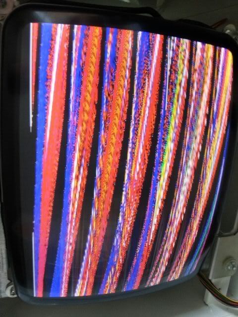
Next up I thought I would try the troublesome F3. I fired it up and was greeted with this:
'Great' I thought. I thought that these monitors were not going to play nice either and that I was going to have to withdraw the NAC from sale but after a quick tweek of the horizontal hold pot on the remote board, bingo bango!:
Outfoxies is fine too
So all in all I'm really happy and it looks like they'll play all of my games and they'll look shit hot too
Next up was modding the white plastic front of the cab with the rotating monitor so that the bezel can be mounted vertically.
Here's the bezel in the horizontal position. As you can see it sits in a slight recess and it screws to the plastic front with M4 countersunk screws:
I had a few ideas about how to mount the bezel vertically but I went with the easiest in the end. I calculated the area of material that needed to be removed and marked the plastic front. The thick lines are there just to remind me which sections I'm removing as its easy to make a mistake when there's plastic shavings flying everywhere:
To route it I just used some scrap pieces of acrylic as straight edges and stuck them to the plastic front using double sided tape. Then it's just a case of carefully routing the excess material off and then using the bearing on the flush trim bit to follow the straight edges.
I did the same think for the bottom corners but I hacksawed most of the material away first:
Centre drilled and drilled some 4mm holes to bolt though, job done:
Test fit!
Both cabs together for reference:
The only downside to the simple method of mounting the bezel I chose is that it sits proud of the recess 1mm. It's not a major problem though and you'll not see it anyway once the front plastics are on.
I'll make two front plastics for the rotating cab, one with a horizontal shape cut out of the graphics and one with a vertical shape cut out and I'll just swap them over when rotating the monitor.
Next thing I want to do is get the speakers sorted as these will affect the front plastics which I want to get sorted next.
This is the speaker mount from one of the cabs:
They both have a single rectangular speaker in the top of the cab above the monitor and a 4" or so round one in the front door. I'm thinking of putting two rectanular ones in above the monitor for dual JAMMA mono and stereo for the boards that support it. Possibly thinking of putting a small sub in the front door :whoopsie: unless it rattles the cab to bits.
For the rectangular ones I've seen [these] that I'm thinking might be suitable? They're shielded and are rated at 10W 8Ohms. I'm guessing I should be able to run them from a little amp inside the cab?
Been busy doing 101 other things but I got the speaker mounts finished this morning, one for each cab:
The original single speaker mount is at the top for reference.
Mounted:
Now that that's done I know where the speaker grill holes need to be so I can get on with the front plastics.
With the speakers in different positions to the original one I had to route some holes in the front plastic so that the sound isn't muffled:
I'll probably use some spacers to bring the speakers forward a little.
In front of this white plastic I'm going to make two clear acrylic sheets. The first one will be 3mm thick and will have the graphics on. I'll then have another clear 4mm sheet in front of that to sandwich the artwork.
The original front plastics has an array or holes drilled in it to let the sound out, I'll do something similar in the two new speaker positions:
One of the castors on the Dinoking is fubar:
I was going to try and source some replacements but after looking at it I should be able to make something for it. I've removed the castor, drilled out the pin and I'll take it into work this afternoon.
Shazaym!
Collected a few parts for the cabs recently:
Wei-Ya PSUs obviously for the JAMMA side of things. I'm going to wire the C&D cab for JAMMA but seeing as I have a spare JVS IO and both cabs have tri-syncs I thought I would wire the generic Sega one for JAMMA and JVS. I can take 5v and 12v for the JVS side of things from the Wei-Ya PSUs but JVS also requires 3.3v so i picked up an adjustable 240VAC>3.3VDC transformer.
I also got a couple of 12v powered stereo amplifiers to run the speakers. The amplifiers come with 12v supplies but from what I've been reading they are not quite up to the job so I bought a couple of higher rated 240VAC>12VDC PSUs which are the two to the right of the amplifiers.
I'm planning on running the mono JAMMA audio through an attenuation circuit and then into that amplifiers as dual mono. I can then also run stereo boards though the amplifier too and control everything from one amp.
I've made a couple of boards to mount the PSUs to. I used the original mount as a drilling template so that I can bolt them to the bottom of the cabinet.
PSUs mounted:
https://photos.smugmug.com/Sega-Minis/i-w7Vqn4M/0/8d829233/M/3psumountspopulated-M.jpg
Installed:
So, the current plan of action is to use the larger top shelf to mount the PCBs on which will leave the middle shelf free. I'm planning on making service panel on this shelf for the power/service/test buttons. I'm going to mount the monitor adjustment board to this and I'll also have a cut out for the amplifier controls. I'll put a voltmeter in the panel and also mount some RCA jacks in for the stereo games and have a 4PDT switch to switch between JAMMA dual mono and stereo.
I was going to relocate the voltage adjustment pots from the Wei-Ya and 3.3v PSUs to the service panel but I've mounted the PSUs so that they are pretty east to access and so that step's not necessary.
I've also sorted some other bits out but I need to pick up some plastics this week, along with peoples marquee materials, before I can do much more with it.
I want to be able to link the two cabs together is a VS/Co-op setup and so I need to come up with a solution for that.
The CPs use 21 way JST connectors too which I'm going to wire up and so I think I'll use the same ones for the link cable. I've actually managed to indirectly get enough free samples to do a couple of CP looms and link cables from JST which is a bonus.
The panel mount cutout for the YLR-21V connectors is the large one to the right of this photo:
They sure are filthy at the moment
I should be able to use that as a template to help cut the ones in the back. I've just ordered a small square file as all of my flat ones will be too big to cut out some of the profile properly.
I'm thinking of mounting the link connectors in the power inlet section at the rear of the cabinet:
I should be able to remove that panel to work on the cutouts which will be easier than trying to cut them in the back of the cabinet its self. Being recessed it should also protect the connectors and allow the cabs to be placed closer when back to back if required.
I stripped the shelves in the second cab of all the parts on the original shelves just like I did on the first one. The 21pin YL connectors and my square file arrived whilst I was doing that so I thought I would have a go at mounting one of them.
As I said in the other post I wanted to mount it in the rear power inlet panel and judging by this picture it looks like there is a lot of space where I could mount it:
But, after removing the panel you can see that there is less room to mount one than you might think but it looked like there would still be room:
I wanted to use the mounting plate inside the CP as a template for cutting out the hole but it was too big to offer up to the panel so I stuck it to some card and used a Stanley knife blade to copy the profile:
I could then stick this to the panel and then transfer the profile using a Stanley knife blade again:
Then it was just a case of chain drilling it to remove the bulk of the material:
and then filing it to fit the connector:
and voilà!
Just the other cab to do now....
Aaaaand, done:
I'm going to cover the cable with some nice braided sleeving later.
I have had chance to make some progress this weekend though
I had some fairly major plans for the marquee holders so I thought I would get to work on them as I knew they would take a while.I had come up with a few designs for holder profiles a while ago:
I eventually decided to make a version of 'B'. A couple of days of hard graft later I've ended up with this lot:
They're similar to the Aero City holders. I decided to go for that style as they are one of my favorite designs with having the large beveled edge
Here's a before and after shot of the beveled edge:
The holder on the right shows the raw edge after cutting the 45 degree angle. It takes two to three hours to polish one of them up to end up with something like the one on the left.
Mounted:
There are a couple of extra parts I needed to make for these holders:
I wanted to be able to light them up like the Aero City holders but as I can only bolt the marquees to the top of the cab it wouldn't be possible to light them using a light box like the Aero and Pony 25. Instead of inserting the marquee holder into a light box I thought I would try and build the lighting into the marquee holder itself.
The idea was to insert some LED strips into the base of holder. I cut a recess in the bottom of the marquee holder for clearance and then made these 'LED mounts':
They're made from 5mm and 3mm white acrylic. The marquee holder is made from 6mm and 2mm clear acrylic so they end up being the same thickness. I routed a slot in one of the pieces so I could feed the power wires through. I used a jig I made a while ago which is really useful for cutting slots.
I mounted some double density LED strips to the top of the LED mounts and wired them up in parallel so that there was only one set of wires I needed to feed through the mount. The C&D cab will have a lot of green in it so I chose green LEDs for that and blue ones for the 'Mini City' cab:
It's always hard to capture LED light on camera but they are lovely and bright 8-)
I then needed to drill a hole in the marquee holder mount and the cab itself. Luckily there was just enough room to drill a 4mm hole at the front of the cab.
I could then install everything. You can see from the cab on the left on the photo below that the mounted LEDs inside the marquee holder recess and below the top of the metal marquee holder mount. The curved acrylic piece is then bolted on the back as shown on the cab on the right. This is to cover it up and stop light shining out the back:
Test time!
Excuse the grubby paw prints, I'll give them a good clean before they are finally mounted.
The LEDs are actually that bright that they shine through the white acrylic, I think I'll line the inside of that piece with some aluminum foil.
It's been a hell of a lot of work on this part alone but I'm really pleased with how it turned out 8-)
-------------------------------------------------------------------------------------------------------------------------------------------------------------------------------------------------------------------------------------------
That's pretty much it for now, my plans have changed slightly and I've got a few more bits to post but I'll post them later. Thanks for looking!


") Thanks for letting me know.
Thanks for letting me know.


:</p><p><br></p><p>[img]https://photos.smugmug.com/Sega-Minis/i-Xf7r2tP/0/badcfaf2/X2/DSC_0133-X2.jpg)


