I recently acquired a Shinobi board looks all original but having a few strange issues. For some reason the right and left inputs are not registering on both the P1 and P2 pinouts but all other controls work. The only other hiccup is the dip switches don’t seem to be changing any settings in the game. All other video and sound seems to be working fine. Any ideas on where to even start trouble shooting? I’ve attached a pic (green tape is on to protect stickers while I give it a good cleaning..she looks to be terribly neglected)

You are using an out of date browser. It may not display this or other websites correctly.
You should upgrade or use an alternative browser.
You should upgrade or use an alternative browser.
- Thread starter Chinzilla
- Start date
A
Apocalypse
I would start at the edge connector and go backwards until the signals stop toggling when pressing a button. Signals go through the multiple optocouplers next to the edge connector.
Looking at your board it's heavily populated with fujitsu and SGS TTL chips, could be one of those faulty, they are well known to be unreliable.
Looking at your board it's heavily populated with fujitsu and SGS TTL chips, could be one of those faulty, they are well known to be unreliable.
Ok using continuity on my multi meter I found where it connects from the edge to the optocoupler. But I can’t find where it goes from there.. should I check while the board is powered on? What tools should I be using to check? Sorry I’m a novice when it comes to finding where the problem is located.
A
Apocalypse
You're going to need a logic probe as a minimum.
Do you think the dip switches not working has any effect on this? Even with the settings set for upright the game is playing in table top (2nd player is upside down) and switched to free play but not letting play without entering credits.
A
Apocalypse
The dipswitches and inputs often have a common part in the circuitry (same data bus) shared using LS245s for instance.
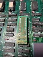
What do you think of this:

I’ve marked in red at the bottom where I’m tracing from the connector where the left input is going.. then above in yellow I’ve noticed some corrosion on the pins of this LS253.. any chance that may be the one that needs to be replaced?
I’ve marked in red at the bottom where I’m tracing from the connector where the left input is going.. then above in yellow I’ve noticed some corrosion on the pins of this LS253.. any chance that may be the one that needs to be replaced?
https://www.ebay.com/itm/184720019529
Would this be a good replacement if that was the problem?
Would this be a good replacement if that was the problem?
A
Apocalypse
Arrgggg... Evil fujisu chips all over your board!
That said the LS253s are a good lead.
That said the LS253s are a good lead.
Last edited by a moderator:
The top and bottom boards are covered with them!!! I will start there and work my way back.Arrgggg... Evil fujisu chips all over your board!
Thats said the LS253s are a good lead.
