What's new

twistedsymphony

Enlightened
Staff member
Immortal
Joined
Jul 21, 2015
Messages
11,655
Reaction score
13,068
Location
NH, USA
I'm trying to build a really simple "supergun" for my bench top setup. I've already got a JAMMA harness wired for controls and power but I need to get the video output setup to go to my LCD monitor (which is capable of 15K and 25K resolutions). I'd like to also include an optional SCART output connector so I have the option of hooking up to my PVM as well.

I'm assuming for the VGA connection I'll want to use a Sync Separator like the LM1881 to break the C-Sync out into H/V Sync?
My other concern however is the voltage ranges. Arcade RGB typically outputs 4V peak to peak but VGA spec is 1V with 75ohm termination. I'm curious how others have handled this aspect of it.

-----------------
JAMMA to SCART seems much more straight forward but but I've seen numerous suggestions for wiring from hooking the output straight to the SCART pins, to using 150ohm resistors, to 330ohm resistors with 220uF caps. I'm interested in what others have used for this in the past... what worked/what didn't?
 
It would be cool to have a simplified "supergun" test bench setup to test different boards/systems. I currently use RGBs HAS with XRGB Mini to test, not ideal because of fiddling with the Mini.
 
Generally with JAMMA to SCART I use 220ohm resistors on R G B and Sync to drop the voltage down. Seems to work fine, and I've used it with tons of JAMMA boards, CPS2, F3, MVS, etc. etc. Some of the JAMMA to JVS converters just use resistors to drop the voltage too.

A 220uf cap with negative towards the display can't hurt, though I'm sure someone else can provide a more technical explanation of that one. Only time I've had to use it to get a stable signal was on a double dragon 3 board that seemed to have shitty sync signal.

You could split sync, but a lot of monitors will just take csync on the hsync pin. It is a quick/easy circuit to split it though if you wish.
 
Last edited:
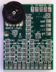
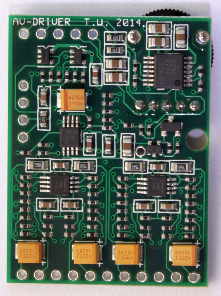
Recently I used one of Tim's AV-Driver boards to connect a PGM (jamma) via scart and the outcome was just perfect...

http://etim.net.au/av-driver/

AV_top_small.jpg
AV_bottom_large.jpg
 
Generally with JAMMA to SCART I use 220ohm resistors on R G B and Sync to drop the voltage down. Seems to work fine, and I've used it with tons of JAMMA boards, CPS2, F3, MVS, etc. etc. Some of the JAMMA to JVS converters just use resistors to drop the voltage too.

A 220uf cap with negative towards the display can't hurt, though I'm sure someone else can provide a more technical explanation of that one.
I think skate nailed it here... By adding a 220uf cap negative out to my RGB lines it helped to clean up random video noise.
It will also brighten up the image, so you may want to test before committing to 220ohm resistors (many use variable/adjustable).

Sync I keep composite but because of the range of different board signals, I run it thru the LM1881 for sync stripping/low pass noise filtering.

This is a shot of my project board before I added the 220uf caps to the RGB lines.
IMG_20150902_113438.jpg


I took everything about the sync from this diagram in the official documentation...
Capture.PNG
 
Last edited by a moderator:
Thanks for the suggestions... I've got some parts on order so we'll see how this goes :)

FWIW the rest of my "super gun" is really just a JAMMA harness with JVS plugs for power and Net-City control panel plugs. this lets me plug in any of my Sega Panels depending on what I need and the JVS supply works with both JVS games or JAMMA games. I also use a Sega JVS 2 JAMMA I/O for the JVS games so that the controls feed back through the JAMMA harness to the panels.
 
I've been revisiting this lately... and I started to do some research into WHY you might use resistors and/or caps as I find understanding the why often leads to implementing the best solution.

If someone knows or can explain better, please correct me; but this is my understanding so far:

Caps:
It's my understanding that the 220ohm caps are there to adjust down the DC offset. So for instance if a signal normally osculates between 2V and 5V applying an appropriate cap may offset it down 0V and 3V, or if dropped lower could even drop it down to something like -2V and +1V. I don't know about the JAMMA signal specifically but I'd suspect that these are not at all needed. These tend to appear on SCART connectors for various consoles because the particular video amplifier used by those consoles requires the offset to be adjusted from the output and the manufacturer omitted them from the internal circuit. An example I've seen mentioned a few times is the Sega Genesis/MegaDrive which requires these caps in the SCART connector because Sega didn't officially support RGB and omitted the caps to save cost and the Neo-Geo AES which uses the same video cable but does not require the caps because they're already integrated internally. Doubling up on the caps would be detrimental to the output signal. I'd suspect they're not needed in JAMMA applications because JAMMA applications already properly prepare the RGB output signal since that's their normal output mode (unlike the Sega Genesis/MegaDrive).

Resistors:
It's my understand that the resistors are there to drop the output voltage (amplitude) from a JAMMA board to something that's more in-line with consumer standards. from what I've read JAMMA RGB signals oscillate between 0V and 4V while consumer RGB monitors expect a signal between 0V and 0.7V (0.7V is the SCART standard as well as the VGA standard, I'm unsure of what the PVM/BVM displays are specifically designed for but I'd assume it's the same).

If you follow Ohms law V = i*R you can calculate the resistance needed to drop the voltage from 4 to 0.7 but only if you know the amperage. (Maybe I'm thinking about this wrong, electrical calcs were never my strong suit) SCART and VGA standard call for 75ohm impedance on the display side which using ohms law and the 0.7V that it expects on the signal line there should be a draw of 9.33mA
knowing that and applying ohm's law again to reduce the voltage by 3.3 (4-0.7) with a .00933 Amp draw would mean that the R G and B lines would need ~353.5ohm resistors which would have to be round down to 330ohm or up to 360ohm to fit within standard values. The Sync signal should be 5V for all JAMMA, VGA, and SCART so there shouldn't be any need for a resistor or cap on that line. I've seen circuits suggesting no resistors, 150ohm resistors, 220ohm resistors and 330ohm resistors. So this leads some credence to the use of 330ohm. Using the same calculations the use of 220ohms would be correct for dropping a 4V signal down to a 1V signal. I've read that despite the standard being 0.7V many displays are setup for a 1V signal... so there's that.

I'd suspect you'd also want to use resistors with a lower tolerance (1% instead of 5%) and/or test out the resistors to ensure they match as close as possible.

I see a lot of Superguns offer trim-pots for the RGB lines and I'm assuming that this is where they're placing them in the circuit. that leads me to believe that not all displays have the same draw or perhaps not all PCBs output at the right voltages (heck even arcade monitors need some adjustments when switching PCBs). my biggest gripe with this is you're eyeballing the proper balance between each of the colors.

An alternative that I've yet to see anyone implement would be to use 2 resistors to create a voltage divider that could drop the signal down to the required 0.7V regardless of what the draw is on the other end. I'm not sure if this would work or if it'd be better or worse than simply assuming a 9-13mA draw.

Most circuits I've seen use the 2-resistor voltage divider circuit to drop the amplified audio output down to line level (usually dividing the output volume by a factor of 10) which made me wonder why the same technique wasn't being used on the amplified video outputs as well.

TLDR;
no caps, and 330ohm resistors on the R, G, and B lines (but not on sync) seems to be the most appropriate solution. though 220ohm resistors may be more suitable for some displays.
 
Last edited:
On my LCD/xRGB mini, CPS2 looks perfect with 330ohm resistors and 220uf caps (negative facing display) on the RGB lines.
Remove the caps and its darker and much noisier.

CPS2 must be a "bright" board tho, because try the same with a Irem M92 (I've tested In the Hunt and R-type Leo) and its way too dark with 330ohm resistors.
I think this is why so many use trim pots, the values are all over the place from board to board.
Did you try lower value resistor or trimmers for the M92? I am trying to figure out how to brighten the board up, the board is just too dark, wanted to see if there is a simple circuit that would boost the rgb signals.
 
wanted to see if there is a simple circuit that would boost the rgb signals
Should be able to use a THS amp for this, but I'm going to assume you are running this in your Vewlix with JAMMA kit?
If so, then you can boost both the incoming signal and then outing going signal with the menu on the scaler board.

I'll try to remember when I get home to get a pic of what I have mine set at with M92.
 
wanted to see if there is a simple circuit that would boost the rgb signals
Should be able to use a THS amp for this, but I'm going to assume you are running this in your Vewlix with JAMMA kit?If so, then you can boost both the incoming signal and then outing going signal with the menu on the scaler board.

I'll try to remember when I get home to get a pic of what I have mine set at with M92.
Cool, thanks.
 
On my LCD/xRGB mini, CPS2 looks perfect with 330ohm resistors and 220uf caps (negative facing display) on the RGB lines.
Remove the caps and its darker and much noisier.

CPS2 must be a "bright" board tho, because try the same with a Irem M92 (I've tested In the Hunt and R-type Leo) and its way too dark with 330ohm resistors.
I think this is why so many use trim pots, the values are all over the place from board to board.
that's weird. removing the caps should theoretically make the boards brighter, they shift the whole signal range down. if I understand their role, they're essentially brightness control. The resistors are more like contrast control since they define the amplitude of the signal/the range from white to black.

Then again the xRGB devices are JP21 compliant not SCART. All of my calcs were based on the SCART/VGA signal standard. i don't know what the JP21 standard is.

I also don't know jack about CPS2 boards, I don't own one, nor have I ever.
 
I've had good success going with no caps and 330ohm resistors.

I first tried no resistors and it was playable and not washed out at all but the images were far too bright, all the whites and bright colors has excessive bloom and bleed. With a 150ohm resistor this was toned down a bit but it was still there.

after 150 I went to 330 and the image was perfect 0 bloom, 0 bleed, not too dark, not washed out. I tested with both my ST-V and my CPS3

14032981_1155218274552705_335202982_n.jpg


13643739_1044656878987125_2090540685_n.jpg


The ST-V has some flickering visible in bright colors that isn't present in the CPS3, for now I'm blaming this on the JVS PSU I'm using since it has several bloated caps and I'd suspect that the CPS3 has better on-board power clean up than the ST-V
 
Out of curiosity, I did a few quick tests with my setup too. Tested most permutations of following attributes, using a NeoGeo MV1FZ board:

- RGB lines with 100 Ohm resistance
- RGB lines with 180 Ohm resistance
- RGB lines AC coupled with 470uF cap
- Sync line as-is
- Sync line dropped to below 0.3V
- Sync line AC coupled with 470uF cap

Target outputs were a Sony Trinitron CRT TV, and XRGB-mini hooked up to a 50" LED panel.

Aside from contrast changes when altering resistance values on the RGB lines, I did not detect(*) any difference in picture quality in any combination. Both the CRT and XRGB-mini handled DC and AC coupled signals equally well, and neither seemed bothered about sync line being grossly hotter than SCART standard allows.

On the CRT, 100 Ohm resistance on RGB lines yielded optimal picture, and with XRGB-mini, it seemed that even 180 Ohms was a bit on the low side - but since the box allows for manual A/D input level adjustment, it was trivial to get a perfect picture even at 100 Ohms.

This leads me to believe that if AC coupling of a JAMMA board video output actually improves something when using a CRT or XRGB-mini, it means there's likely something fishy with either the specific board in question, or the supergun. My first go-to fix attempt would be replacing all electrolytic capacitors on the board, if they are original. I noticed that on my CPS-1 board, the picture alignment changed considerably after recapping and now it's perfectly centered.

Further reading about AC coupling video signals: https://www.maximintegrated.com/en/app-notes/index.mvp/id/3303

(*) I would need to setup a capture solution for side-by-side comparisons, then possible differences would become much easier to detect.
 
Last edited:
Resistors:
It's my understand that the resistors are there to drop the output voltage (amplitude) from a JAMMA board to something that's more in-line with consumer standards. from what I've read JAMMA RGB signals oscillate between 0V and 4V while consumer RGB monitors expect a signal between 0V and 0.7V (0.7V is the SCART standard as well as the VGA standard, I'm unsure of what the PVM/BVM displays are specifically designed for but I'd assume it's the same).

If you follow Ohms law V = i*R you can calculate the resistance needed to drop the voltage from 4 to 0.7 but only if you know the amperage. (Maybe I'm thinking about this wrong, electrical calcs were never my strong suit) SCART and VGA standard call for 75ohm impedance on the display side which using ohms law and the 0.7V that it expects on the signal line there should be a draw of 9.33mA
I'm also trying to convert JAMMA to VGA (CGA) but I'm wondering if your calculations might be wrong?

According to Wikipedia (and other sources), VGA is double-terminated and not only terminated on the display side with a draw of 18.7 mA.

Therefore, R = (4.0 - 0.7) / 0.0187 == 176 Ohm. (4v RGB, 178 Ohm standard size)
...or R = (5.0 - 0.7) / 0.0187 = 230 Ohm. (5v RGB, 220 or 240 standard size)

Regardless, I'm still confused because Andy from Ultimarc (creator of J-PAC) says that he outputs 5v p-p and not 4v and that I should use 220 Ohm resistors. Furthermore, I've read that arcade PCBs can use anywhere from 2v - 5v so maybe that's why many RGB transcoders have pots?

Are there any ICs that we can use in a simple circuit to detect the correct p-p voltage of the RGB signal and correctly scale to 0 - 0.7v?
 
@twistedsymphony Your post was very helpful, thank you. Have you noticed a difference using 330ohm vs 220ohm resistors connected to a scaler like the OSSC or RT5X or does it not matter as much since it's converting the signal from analog to digital? My guess would be as long as sync output = 75ohm, its safe for the scaler..

No need for caps still?

I'm making a scart cable.. :)
 
Last edited:
. Have you noticed a difference using 330ohm vs 220ohm resistors connected to a scaler like the OSSC or RT5X or does it not matter as much since it's converting the signal from analog to digital? My guess would be as long as rgb output = 75ohm, its safe for the scaler..
I've never tested this on a scaler as I use it on my bench setup which is a CRT (Sony PVM display). There's no reason using resistors would cause a problem with a scaler though, I'd even argue that it might be safer doing so.
 
The Jassifier device I released accepts arcade PCB video and outputs SCART levels with the option to switch between 75ohm and TTL sync (with pots on RGB lines to dial in color levels).
It could be used in any project that seeks to turn arcade leveled output into SCART/device level safe output... Just say'n. *shrug*
FbSR1IK.jpg
 
Last edited by a moderator:
Back
Top