What's new

ArcadeMachinist

Professional
Joined
Nov 30, 2018
Messages
160
Reaction score
359
Location
Florida
No, this is not an overgrown kiddie-ride.

This is (I believe) rare full motion cabinet with Cruis'n USA game.
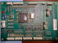
It has standard CUSA pcb, which supports motion, if correct DIP is ON and special motion handling extra boards are connected, which it has plenty.

This cab has some problems with PCB randomly rebooting, but I guess it is just due to re-cap is needed.
When PCB runs - there is no motion. First of all mechanical safety switches were stuck, after cleaning them - now it's safety opto sensors block.

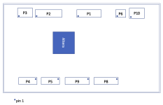
Opto emmiters and receivers are built into the base and all four front sensors are missing for some reason.
I already did some research and drafted/ordered custom PCBs and parts for these 4 detectors.

Safety diagnostics screen also suggests there are safety mats.
I guess these are step-on trigger mats, that would go on the floor around the car, so the motion stops when someone is too close.
I was not able to find any info on those. All (quite a few in existence) Youtube videos with the game running do not show any mats around the car.

I wish I had service manual. It does not exist in digital form and was only twice for sale on eBay in past 10 years.


5a579f7a-b208-406a-b6c4-02740ba3f582.jpeg2022-11-06 21.53.35.jpg2022-11-06 21.53.39.jpg2022-11-06 21.54.23.jpg


I would post detailed research data and pics here.
This cabinet is suprisingly poor documented online.
 
Try hitting up Doc MacK over at Galloping Ghost Arcade. He has seen some rare cabinets in his day and may have the resources to get you that service manual. Or perhaps leads on how to obtain it.

Good Luck!

Del
 
Wanted to post some obscure things not documented on the 'net at all.
Ladies and gentelmen, Midway/William's/Nintendo motion safety PCB.

It does control:
4 IR emmiters (P4)
4 IR receivers (P2)
4 step on safety mats (P8, P9)

My cab had only emmiters and no receivers.
I have managed to score 5pcs of these receivers from a Pinball shop, whihc got a bunch of unknown Midway parts from somewhere.
Even before that I was able to identify PCB layout and parts used from a photo and designed/ordered some repro boards.

Emitters/Receivers use some special logic. They are not just simple on/off barriers.
Each emitter's beam can be seen by three (of 4) receivers and the control pcb is manipulating on/off states of the emitters and then checks if designated receivers do see the beam.
So not so easy to trick it, if you want to run without the actual sensors.

I have manged to install new sensors and replace dead IR leds in the emitters, now just 1 sensor does not want to work, alternating between "ok" and "opto beam broken".
I suspect it is a wiring problem somewhere in between.

As for the safety sensor mats - I was able to find zero info on them.
There are 4 pin connectors for each one of them (Front, Left, Back, Right) with pin 4 being powered by 12VDC, pins 2&3 are connected together via 10kR on the PCB (loopback) and pin 4 seems to be the real "sense" pin, it goes straight to BA19339 comparator.

Also all the videos of the cab on YouTube do not show any mats around. I wonder if that can be just disabled.

Both motion safety PCB and motor control PCB (GALIL Motion Controls) are connected via standard steering wheel control board.
The main PCB itself is also a standard one, as in any other CUSA cabinet.
 

Attachments

  • 2022-11-18 17.22.14.jpg
    2022-11-18 17.22.14.jpg
    280.3 KB · Views: 74
  • Screen Shot 2022-11-18 at 5.24.06 PM.png
    Screen Shot 2022-11-18 at 5.24.06 PM.png
    30.8 KB · Views: 72
I have reproduced opto barrier sensor boards using a modern detector.
Looks like the modern one is much more tolerant to noise and has better sensitivity.
Opto-barrier works fine now. Next step is to figure out how to trick it into believing there are safety mats connected.

Pic: 1 original sensor with 5 repros.
2022-11-28 01.16.10.jpg
 
Updating:
I have managed to rebuild sensors and to override (missing) pressure mats.
One of the motors moved all the way up. Two other are completly stuck.

Tried to connect lab PSU to power front motor directly and it does not move a bit, even when 80v at 13amps pumped into it.
Had to remove actuator assembly, and that's a nightmare. Took me like 3 hours. Not sure how they did mass-production install at the factory.
There is basically not enough space for you to get to it with the tools.

Anyway actuator removed and it is completly stuck because of dried grease.
Not sure what they used for grease, but it is immune to de-greaser. However WD40 washes it away easily.

When separated from the worm shaft - the motor itself happily (and slowly) runs with just 15v @ 0.4amps

I'm thinking about making full rebuild, with pulling all the parts out, repainting the base, etc.
Given amount of time needed to remove 1 actuator it is not much difference.


2023-07-06 23.28.07.jpg2023-07-07 09.47.38.jpg2023-07-07 09.51.32.jpg2023-07-07 11.02.50.jpg2023-07-07 13.57.33.jpg
 
Last edited:
Nice work dude. That cabinet is amazing - I've not seen any modern accounts of them, only promo material. Hope you get it running again!
 
Agreed. Lots of work! Hope this pays off in the end. That would be amazing!

Del
 
Back
Top