spacejockey
Enthusiast
Hello everyone,
I'm reaching out because I'm having some issues with a game and I got to a point where my skills are at their limit and I need help.
I recently purchased an m72 Dragon Breed game that I have been trying to find for a long time.
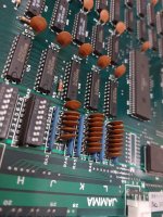
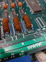
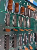
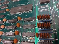
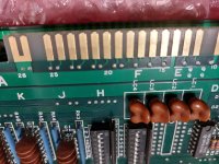
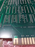
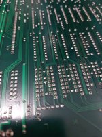
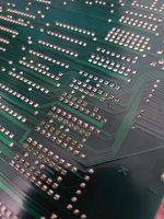
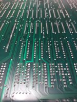
The game and the boards look clean, altough I have a lot of trouble making it work on any my 3 cabs.
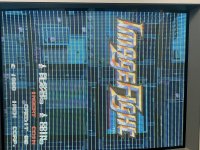
Most of the time the game starts with "RAM ok and ROM ok" screen test ; then goes to the disclaimer message for use outside of Japan ; and then stay stuck there.
No title screen appears, and no joystick or button seems responding at this point.
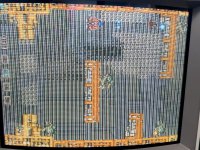
The few times I managed to start the game (on any of the cabs I own, except one) , there is always a problem with the controls ; It's either the joystick doesn't go down, or the jump button is not responding, the rest works fine.
But it is impossible to play and enjoy it with those handicaps.
I have been trying to set different voltages (from 4.6v to 5.1v), but it still gets stuck at the same message.
The 12v seems quite high ; for example if I set the pcb at 5v, it will show 13v instead of 12v, and if I set it at 4.7v, it will show 12.6v.
Also I haven't been able to get to the test menu with the right dipswitch set ON, justy a white frozen screen appears
After a few days of intense trials, I managed to pass the disclaimer message ; but then the game played with some issues (joystick doesn't go down, or the jump button doesn't react). and if I swicth the power off, when I restart the cab (with the same voltage), ... the game gets stuck again on the disclaimer message.
I tried the game on 3 different cabs, an Euro one called N'styl (with scart and tv screen), a Sega Aero and a Medal Game that was transformed as a mini JAMMA cab (scart and tv screen too) and a sega Aero (all original, psu, crt screen and gear, all recapped in 2020).
Like I said after way too many trials, it worked a few times on the euro cab and the medal game, but the worst one was on the Aero, the game stay stuck to the disclaimer screen too, but the screen jumps all the time, haven't been able to get rid of the jumping and get the game to start so I didn't insist on this cab.
According to the seller, the game played smoothly at his place.
It ran at 4.9v.
The pcbs have been recapped since 2022, there also was a repair on a TTL componant, but the seller couldn't remember which one and the person who did the repairs haven't answered me yet.
I am at the end of my wits guys... can someone relate ? Have you ever encountered such issues on a Dragon breed pcb or any M72 gmae ? Am I doing something wrong ? Is there something I can do to make the game work ?
Thanks in advance for those who will help with this.
Trying to upload videos too, but having a hard time doing it.
ps: sorry if my english doesn't make sense sometimes, trying to improve on it


