What's new
Okay, I decided to introduce a problem to check the P Bus cart, so at least I know what to expect.

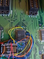
I've decided to remove the input from the NEO-244 at location C2, thats for P Bus Buffer marked a "P4" Pin 19
https://wiki.neogeodev.org/index.php?title=File:NEO-244_mv4ft_c2_pinout.png
the yellow wire to the right thats not connected

PXL_20230504_130313319.jpg

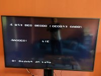
I've expected this to show up as error, instead I got a garbled screen thats counting, like on slot 2 and 3:
PXL_20230504_130319028.jpg

@ack I'm either confused or I've found a bug (I'm confused a lot lol)
I think you are confusing P ROMs and P Bus? The diag board is for testing access to the P ROMs on the PROG board. P Bus is the multiplex address bus used to access C and S roms on the CHA board. The goal of the diag board is help track down why a board is not detecting carts (crosshatch issue).
 
On a side note @ack , what is the likely hood of making an extra PCB for the M1 ROM?
I was on the hunt for repros/fakes/conversions for months so I did not have to sacrifice an original game, but if that could be custom made, selling kits or assembled all-in-one carts is not a crazy idea ;)
From what I understand its the ZMC that is needed, I was not able to find it on Ali (not all items/sellers are available in Europe for some legal reasons).
I bought a few from here after @hatmoose mentioned it

https://www.aliexpress.us/item/2251832763681253.html

The NEO-ZMC chips I received were legit and of the few I tested, worked fine. However in the time it took for them to arrive I got busy working on different project, so the diag CHA board is on the back burner for now.
 
I think you are confusing P ROMs and P Bus? The diag board is for testing access to the P ROMs on the PROG board. P Bus is the multiplex address bus used to access C and S roms on the CHA board. The goal of the diag board is help track down why a board is not detecting carts (crosshatch issue).
Oh.. you're absolutely right, I was confused :D
The connection to the P(rogram) ROM is checked, not the P Bus, thanks a lot for that explanation :)

I bought a few from here after @hatmoose mentioned it
Yeah they don't sell that in Europe it seems :(

Screen Shot 2023-05-04 at 7.13.02 pm.png
 
Depending on how many you are after I can either sell you a few from what I got or I could proxy buy some for you.
 
I've been wanting to do this for a long while. One of the deficiencies of the neogeo diag bios is the inability to help when a motherboard boots to crosshatch. I decided to take a stab at creating a custom prog board to help with this situation. With it, its possible to verify P rom output, address/data lines, and p2 region is writable (carts use this for bank switching).

I started with a proof of concept using breadboard with 2 extra 64K sram chips I had. I wired them up to a P rom socket along with a couple 74 series logic chips to handle enable/write logic.

prog_bb1.jpg


I wrote up some test code to verify it was working as I was expected and it seemed to be. But 2x64K is only 1Mbit of the 8Mbit address space I would need for full testing. I found some 8Mbit 16-bit 5V srams on digikey and got one wired up.

prog_bb2.jpg


This worked well too. This breadboard setup made it easy to simulate errors to very the new code in the diag bios was detecting the errors.

Next step was to get all this on a pcb. This was the initial version

prog_proto1.jpg


Thankfully it worked. The only issue was a little bit of side to side play when the board was in the slot, which I fixed in the next revision.

Its hard to tell from the picture but there are through holes for each signal (and signal labels) to make it easier to debug crosshatch/slot issues.

In the above picture I ended up soldering in some right angle connectors in the through hole to make it easier to test some stuff related to the board design. The breadboard is me wiring up a couple signals related to the P rom to LEDs because they aren't something you can test for from the CPU. This will let you verify the signals are becoming active during the test loop.

This is the latest revision and where things are currently.

prog_proto2.jpg


There are still a few things to do
  • A couple minor tweaks to this MVS version
  • Finish up the AES version (95% done)
  • Write up docs on the different tests
  • Go over diag bios changes again
That's amazing @ack where you took the neodiag bios after the disassembly.
@maki was kind enough to sell me one of his extra pcb's, looking forward to try it myself.
 
Gently modified to suit local conditions :)
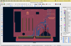
Screen Shot 2023-06-23 at 6.28.39 PM.png
I cut a big hole so the M1 from the CHAR board underneath can poke through, added a couple of extra (inert) 40 pin ZIF sockets for spare BIOS storage, and adjusted the location of the LED's to accommodate. Feels like I may have just drawn a moustache on the Mona Lisa...

Into manufacturing now - I'll know if everything lines up in 14-18 business days

Edit: in the (very unlikely) event that anyone wants my mangled files, attached.
 

Attachments

  • Hacked up board.zip
    253.3 KB · Views: 61
Last edited:
Nice work. Was going to suggest a fingerboard that solders/connects to this board with stand-offs for the CHA slot, and put everything you need for PROG+CHA diagnostics on this PCB... you should be able to easily fit everything in the footprint of a single board with modern parts?!?

Many years ago I produced some adapter boards for a long-aborted (stalled?) project to produce flash carts for the Neo Geo. I got as far as producing finger boards and a breakout board with euro connectors. As a result I could plug the breakout into either MVS or AES and have the bus pins mapped to consistent pins on the euro connector. Using them I had an AES cart plugged into an MVS running and working - without sprites of course. FWIW the flash cart PCB was laid out but never properly reviewed or produced.

AES adapters
AES cart running in an MVS board
 
I started working on the CHA board, first revision of the board arrived today and is working.

IMG_1028.jpg


I decided to keep the roms near the middle for now. Having them on the outsides of the board looked like a nightmare for trace routing and didnt want to deal with it on the first revision. I'm not sure if I will attempt to move them or not as it just saves $1-2 from not having to buy a low profile sockets (assuming I also updated the prog diag board with cut outs). Plus its been 3 years since I've touched the diag M1 rom, so just soldering doesn't seem unreasonable to me.

The design is dependent on the NEO-ZMC chip. While waiting for the boards to be made I've been spending some time looking into what would be required to replace it with a CPLD. The smallest I could find that should have enough macrocells to work is the 44 pin plcc/tqfp versions of Atmel ATF1504AS or Altera EPM7064S. Both of these are 5V parts but are out of stock everywhere. I have a couple ATF1504AS coming from ebay that i'm going to play with, but ultimately I don't think it will make sense to use them on the board since you can get original NEO-ZMCs from china for $2.
 
Thank you very much for your amazing work, it looks absolutely awesome and the ability to make a fully functional test cart without needing to sacrifice and existing cart is a huge step forward.
 
The first AES revision showed up, but ended up having a bug. I accidentally swapped CA4/SA3 in the schematic on the board edge, which caused S1 A3 to be wrong. Cut the the bad trace and added a bodge wire (on the back side of the board), which fixed it. There are a few more minor tweaks I'm going to make in the next revision.

IMG_1033.jpg


I've also been looking at the CPLD replacement for NEO-ZMC.

IMG_1029.jpg


It works, but still not sure about making a board with it. My concern is with this being opensource that it be as easy as possible for other people to program the CPLD. However programming the CPLD seems like a total pita to do. I'm curious if anyone has any suggestions/advice to make it easier.

I've been using Atmel ATF1502/AFT1504, which are still actively being produced. There seems to be 2 ways to program them.
1. You have a fancy eprom programmer that supports programming them + a plcc44 to dip adapter
2. Programming via JTAG, which seems to require Atmel's (free) programming software, but it only works with their $90 usb jtag programmer

Additionally those CPLD's are pin compatible with Altera EPM7032S/EPM7064S. These support being programmed via JTAG using a $10 USB blaster, but unfortunately these CLPD's are no longer in production. I wouldn't want to tell people to use those since they would be forced to buy them from a random person/china and risk getting fakes.
 
I found a cheap/easy way to program the atmel cplds using this programmer and openocd.

programmer_and_cable.jpg
programmer_plugged_in.jpg


So I went ahead and created 2 cpld variants, a 44 pin tqfp and a 44 pin socketed plcc version.

neogeo-diag-mvs-cha-atf150x-tqfp.jpg
neogeo-diag-mvs-cha-atf150x-plcc.jpg


I've put these and the neo-zmc version of the mvs cha up on github

https://github.com/jwestfall69/neogeo-diag-mvs-cha

It will be a couple weeks for the aes versions, waiting for the boards to be made.
 
Working on MVS CHA.

In parallel DJsheep sent me this awesome project https://github.com/wickerwaka/PicoROM which is an emulator for DIP32 EPROMS up to 2mbit

I have been been looking for an excuse to get some picoroms made, and it feels like this is it.

Am I oversimplifying here, or could I manufacture the 5v version, rotate the USBC header so it fit correctly, and jobs done?
 
Back
Top