Good sleuthing. Let's step through it:
"SNA" in this case is Sound CPU Address Bus (as opposed to SND which is Sound CPU Data Bus). The bus is shared by several devices:
- Sound CPU (schematics page 6)
- Custom 30 (sound control custom) (schematics page 6)
- HM6264 sound RAM chip (schematics page 6)
- Custom 121 (sound CPU address decoder) (schematics page 6)
- Two LS257 TTL chips located at P3 and N3 (schematics page 6)
- Three LS257 TTL chips located at K1, L1 and M1 (upper-left corner of Page 7)
- J1 DIN connector that connects to the ROM board (Page 8 ).
Fortunately it's only SNA lines 12 and 14 that appear to be culprits - that narrows our scope a bit. You were wondering what the "source" is for the signals. The answer is the Sound CPU - it sets the address lines for whichever EPROM or RAM addresses it wants to read in, as well as the addresses it wants to write data out to. Customs 30 and 121 work with it to make sure data from the correct sources flow in, and processed data goes out to the appropriate destination. The customs are also "black boxes" in that there isn't any formal documentation for them, although we can deduce some of their behavior from the schematics. There's also some TTL chips that manage some address & data line communications to a memory chip located at H1 that is shared between the main/sub CPUs and the sound system. We're getting into complex territory here unfortunately.
Let's keep it simple for now by verifying continuity on the suspect lines between all the components that use them. A damaged trace is far preferable to a failed Custom. Fortunately we can rule out Custom 30 as a culprit since you cross-checked it with your other board. Let's focus on SNA12 first.
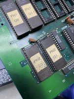
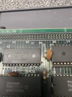
- Check continuity for the J1 pin connector - it's responsible for feeding data from the ROM chips on the game board into the CPU board. SNA12 is Pin A40 on the connector, although SNA14 is not connected. Your multimeter should read continuity between J1 Pin A40 and Sound CPU Pin 20. Also detach the ROM board and make sure there isn't a missing or bent pin inside the connector. SNA12 runs through the connector J1 over to the two sound ROMs in the lower-right corner of the ROM board located at A10 and B10, on Pin 23 of each chip (page 8 of the schematics).
- SNA12 also connects between the Sound CPU, HM6264 sound RAM at location U3, Custom 121, and Custom 30. Verify continuity on the SNA12 line between each of these components.
- As best as I can tell, SNA14 is only used between the Sound CPU and Custom 121 - I'm not finding it anywhere else on the schematic. Verify continuity on that line between those components.
There's a lot more we can test, but let's keep the focus narrow and check these first. Fingers crossed you find a broken trace somewhere in the SNA12 chain!


