Chaotic-Strike
Student
Man that poor little guy even had his pad torn outOkay, resistor is reattached. So now just waiting for that new power supply.
Before and after.
 hope this works out for you and fixes the problem
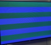
Start by testing your new power supply under load. Do you have a crummy board that you can test with? Plug the power supply in and read the +5, -5 and +12 volts.My new power supply came in and now it’s giving me this screen when I power the board up on the Retrotink. I only left it on for a few seconds. So I’m guessing that I better just clip that resistor to what it was before or did a chip fail or come loose or something?
Did they try to desolder the broken leg of that resistor? I hope they didn't rip out the plate-through as that could cause a short. All they had to do was add a little solder to it and reattach.Okay, resistor is reattached. So now just waiting for that new power supply.
Before and after.
I have a multimeter that I got a while back to test the Power Supply, but I don’t have another board.Start by testing your new power supply under load. Do you have a crummy board that you can test with? Plug the power supply in and read the +5, -5 and +12 volts.
I’m not sure it wasn’t too long of a job, about a min or two, but the pad which the resistor needed to connect to is gone now. Originally the resistor wasn’t attached there at all, and it was just a pad there. Is there anyway to check or do I just need to go back and have them check for a short or to add a pad back in? To clarify this is a dev board and I talked with who owned it before me and they said this. So that’s why I brought up and asked if I should just clip it again.Did they try to desolder the broken leg of that resistor? I hope they didn't rip out the plate-through as that could cause a short. All they had to do was add a little solder to it and reattach.
Where on the board is R152 located? Any of us could take a look to see if it exists or notI have a multimeter that I got a while back to test the Power Supply, but I don’t have another board.
I’m not sure it wasn’t too long of a job, about a min or two, but the pad which the resistor needed to connect to is gone now. Originally the resistor wasn’t attached there at all, and it was just a pad there. Is there anyway to check or do I just need to go back and have them check for a short or to add a pad back in? To clarify this is a dev board and I talked with who owned it before me and they said this. So that’s why I brought up and asked if I should just clip it again.

About the multimeter. Ok then the safest approach would be for you to back the power supply all the way down while powered off and then power it on and slowly increment it up while monitoring the +5V line until you hit between 5 and 5.10 volts. Then take a look at your -5 and +12V and make sure they are reading good as well. Test your voltage at the JAMMA edge or even better on the +5VCC AND GND pins of any of your chips. JAMMA edge is the easiest place to test though.I have a multimeter that I got a while back to test the Power Supply, but I don’t have another board.
I’m not sure it wasn’t too long of a job, about a min or two, but the pad which the resistor needed to connect to is gone now. Originally the resistor wasn’t attached there at all, and it was just a pad there. Is there anyway to check or do I just need to go back and have them check for a short or to add a pad back in? To clarify this is a dev board and I talked with who owned it before me and they said this. So that’s why I brought up and asked if I should just clip it again.
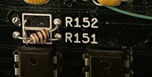
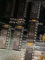
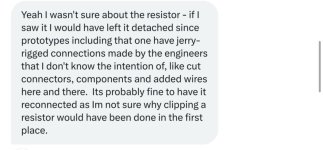
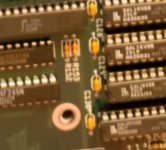
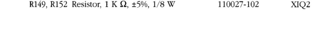
I already found it on an OG board. It’s located in a different spot on mine. 2nd image is from the arcade manual for the resistor in a regular board. The third image is what it looked like before the reattachment attempt on my board. Last picture is one of my board.Where on the board is R152 located? Any of us could take a look to see if it exists or not
Interesting thing is the document you show has a 1k ohm resistor but the picture of yours shows a 10 ohm resistor … I can’t make out what the other board has in its place, it’s too blurry.I already found it on an OG board. It’s located in a different spot on mine. 2nd image is from the arcade manual for the resistor in a regular board. The third image is what it looked like before the reattachment attempt on my board. Last picture is one of my board.
Okay, I’ll test it when I get off work tonight or tomorrow since I’m off then. Do you think I should just go ahead and clip that resistor that was put back on since it likely started the whole problem ?About the multimeter. Ok then the safest approach would be for you to back the power supply all the way down while powered off and then power it on and slowly increment it up while monitoring the +5V line until you hit between 5 and 5.10 volts. Then take a look at your -5 and +12V and make sure they are reading good as well. Test your voltage at the JAMMA edge or even better on the +5VCC AND GND pins of any of your chips. JAMMA edge is the easiest place to test though.
If it’s missing a 1k - 1/8 watt resistor I would purchase a set of these and replace accordingly. I’m a guessing this isn’t your problem though but you never knowOkay, I’ll test it when I get off work tonight or tomorrow since I’m off then. Do you think I should just go ahead and clip that resistor that was put back on since it likely started the whole problem ?

A 10 ohm resistor is a lot different than a 1k ohm resistor also …. Who soldered this resistor back in for you? And why didn’t they test the bird after their work was complete? Very OddOkay tested the voltage on the battery and that was fine. Got the same error. So I went ahead and just clipped the resistor and it works fine again. Thats odd that they put one on there only for it not to work, but hey I’ll take it. I did noticed signs of where they clipped other resistors. I also tested the board on my monitor instead of my TV, and no lines artifacts either. This is one fickle board.
 glad it works again though
They just soldered the resistor that was already on the board, but it was disconnected. I don’t think they had the equipment to power the board up. There’s not alot of options in my area lolA 10 ohm resistor is a lot different than a 1k ohm resistor also …. Who soldered this resistor back in for you? And why didn’t they test the bird after their work was complete? Very Odd
I gotcha, got to work with what you’ve gotThey just soldered the resistor that was already on the board, but it was disconnected. I don’t think they had the equipment to power the board up. There’s not alot of options in my area lol