What's new
I have ordered the S16b and S18 boards along with parts from digi-key. The parts won't be sent until August, though :( Looking forward to building my first boards!

Also finally ordered the board to build an FD1094 security chip programmer. Looking foward to putting my boards back to stock SEGA code!
 
New design to run off an Ardino ATMega2560

1699290514369.png


DescriptionQuantityPCB LocationDigikey Part No.Comment
Cap Cer 0.1uf 25V1C1BC1154CT-ND
Res 10K OHM 1/4W 5%5R1,R2,R3,R4,R510KQBK-ND
Switch Tactile SPST-NO 0.05A4EG1829-NDblack switches for up, down and select, attract
Switch Tactile SPST-NO 0.05A1EG1830-NDred switch for reset
CONN IC DIP SOCKET 14POS TIN23M5462-NDsockets for CD4066BE chips
CD4066BE chip2
296-2061-5-ND
CONN HEADER R/A 3POS 2.54MM
1
952-2245-ND
cut off one and use it for the reset pin
use the 2pin for the SCL and SDA pins
Conn Header 10POS 2.54mm1

2057-PH2-10-UA-ND
connects to the Sega16 multi board - make sure pin 1 matches
CONN HEADER VERT 20POS 2.54MM22057-PH1-20-UA-NDYou will need to cut these for the pins that mount the board to the Arduino UNO
OLED 128x641Amazon URL:
https://www.amazon.ca/Display-Modul...0.96+inch+oled+128x64&qid=1647185028&sprefix=
0+96+inch+oled+128x64%2Caps%2C52&sr=8-5

This arduino 2560 board is the one I am using:

https://www.amazon.ca/dp/B01H4ZDYCE?psc=1&ref=ppx_yo2ov_dt_b_product_details

The SCL and SDA on the pcb need to go to the following locations on the 2560 board

SDA = pin 20 on 2560
SCL = pin 21 on 2560

Loading HEX to Arduino

Here is the hex file needed to program the Arduino UNO:

Sega16 UNO Selector Hex File

** Note: If download does not work, copy the link and paste into new window

You can use a program called XLoader
Connect the board to your computer via USB A and USB B cable
Launch XLoader

1683563896419.png


Choose the hex file to load
Make sure the device is Uno(ATMEGA2560 )
It should find your board
Once set, click upload the program the UNO with the hex file


Attached are the gerber files
 

Attachments

  • sega16-selector-uno.zip
    32.3 KB · Views: 34
Last edited:
Here is the new board
 

Attachments

  • image.jpg
    image.jpg
    201.9 KB · Views: 94
is there a new file for this pcb to be printed from?
 
I think the link for the hex file is down. can you upload the hex file?
 
I put together a few of these but it did not power on. I connected the 10 pin cable to the multi game board but nothing came up so does the arduino need a 5v or 12v powerconnected to the dc jack?
 
I think the arduino and ypur board are plugged together correctly but the oled still isnt displaying everythimg. I plugged in the power from usb and the arduino 2560 lights up. Does the dip switch that is on the game board need to be set to all uo or all down?
 
Last edited:
I connected it to my pc usb 5v and the oled still is not showing anything it doesnt function yet. I connected the reset wire to that 4th pin on the s16 mainboard too but that makes the screen blank and flicker when I click the selector buttons. Does it need to have a 5v vcc from the s16 main board?
 
I dont think the 2560 arduino has wifi so I am not sure it will work for wireless game switching?
 
@BladeZX , your note says " Make sure the device is Uno(ATMEGA2560 )", your image shows what I am getting, "MEGA" not Uno.

I have uploaded the HEX and am getting no response from the OLED also, this is the new design with the smaller OLED and atmega2560.
 
OK I will try and get mine out and run thru some testing to see if I can reproduce
I am going to be very busy this week
Over the weekend we deployed a big project into Production at work so things will be crazy this week
I had 91 hours at work last week and I am beat up
 
I was using a normal mega 2560 arduino so thats not the right one so maybe thats the issue with mine. Maybe it can work anyway but im not sure. My board isnt really in a place with wifi anyway
 
Last edited:
I was using a normal mega 2560 arduino so thats not the right one so maybe thats the issue with mine. Maybe it can work anyway but im not sure. My board isnt really in a place with wifi anyway
I got a note from @BladeZX and he let me know that the new version is NOT setup for wifi game swapping, it was designed to be installed on CP or inside coindoor, but NO wifi swapping.
 
I got a note from @BladeZX and he let me know that the new version is NOT setup for wifi game swapping, it was designed to be installed on CP or inside coindoor, but NO wifi swapping.
Once @BladeZX gets a chance to see if he can reproduce any issues we are having here, I have extra PCBs I printed for the new one with the 2560.

I should also have a stack of the original Pi Zero W boards printed this week, if anyone needs them, drop me a DM. Most of the price is the shipping from China so I usually max out any boards I have made up before it hits the next big jump.

Also, if anyone is in the market, look at micro center if you have one near you. I just picked up the Pi Zero W tonight for $15 which seems to be way lower than anything else I can find.
 
Raspberry Pi Zero W was used for this multi selector.
I bought the RPi Zero W with the pin header already soldered to it

rpi-zero.jpg


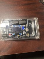
This is the case I am using for it:

rpi-zero-case.jpg


You will also need a 8GB microSD card (I recommend Sandisk)

Here is the Raspberry Pi image you will need to load to the RPi. Just unzip it and load the img file using Win32DiskImager

Sega16-Pi Raspberry Pi Image

The pi user is: pi
The pi password is: segamulti

Here are the RPi connections that will be used and connected to the Sega16-Pi mult selector pcb

sega16-rpi-connections.png


Pins 1,3,5 are used for the OLED display
Pins 11,13,15 are used for the UP, DOWN and SELECT buttons
Pins 8 and 10 are used to send and receive data from the Atmega328 chip
Pins 12,16,18 and 32 are used to program the Atmega from the Raspberry Pi

Connect a USB to microUSB cable from the multi selector to your RPi in order to power everything from one place

You also need to make a connection from the Sega16 pcb to the VCC, GND and RST pins on the multi selector
Red is VCC (5v)
Black is GND
White is RST
IMG_20200416_213545.jpg
I got this first one built tonight. Couple questions @BladeZX (when you get a chance, I know you're swamped right now)

1. What is 8gb! is the micro holding all the rom files also? It seems crazy big for code to switch games? I would love to get away from using all those 322s if I can!

2. Would you be okay if I used your KiCad file to modify this to change pinout location so we could mount the Pi Zero from below directly to the switcher pcb so the only cable needed would be 5v GND and reset to the PCB? I think there is a ton of room avail that hangs off the side of the multi card where we could slip the Pi up and under?
 
Back
Top