YesAffinity
Enthusiast
I have a Neo 25 w/ Toshiba A59JMZ90X and Toei TC-A252S chassis.
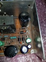
I recapped the power supply a few months back, no issues. I decided to pull the Toei chassis to recap it, due to developing some noise/interference in the image. Otherwise, the monitor/chassis have worked great for as long as I've owned the cab (5 or 6 years now, I believe), and the monitor has always been crisp and bright.
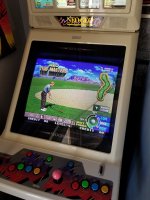
I completed the cap job, connected everything back up, and it ran seemingly normally for about 30 seconds. I saw the Unibios boot screen and Neo Geo startup screen. And then, video disappeared and the cab started producing a high-pitched "squealing" sound.
Video of the squealing, here:
View: https://youtube.com/shorts/dMfFvDcDhQU
Pulling the chassis and inspecting my work, I found C67 reversed. I corrected that, reconnected everything, and no improvement
Quite a bit of poking around, reflowing many things, re-re-checking all of my work, no improvement.
I decided to connect the chassis power to a variac while powering the cab normally. I plugged the monitor/chassis into the isolated socket with the lowest voltage, at just over 100V. The squealing was significantly reduced, almost non-existent. Still no video, but that's something. I then turned the dial on the variac, which would increase that outlet to around 105V, and the squealing increased.
I'm guessing this has something to do with voltage regulation on the chassis.
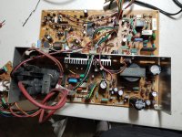
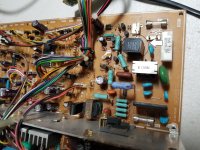
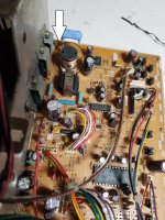
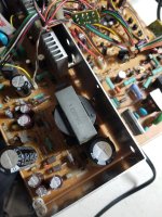
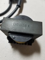
So, I pulled the chassis and plugged into the variac on the bench. Same result, not connected to a monitor. It's hard to tell exactly where the noise is coming from, but there are 2 components getting extremely warm to the touch (circed in the picture).
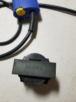
I also am able to hear something "turning on and off" when power is turned on and off, sounding like very normal operation - a single switching or clicking sound, one at power on and one at power off. Sounds like that's coming from the flyback. I'm staying hopeful and considering that a good sign for the time being.
I also confirmed the cab plays blind with no chassis.
1) Has anyone experienced this issue before and/or have any insight into the issue?
2) Are there other more common chassis that will work with this tube?
-Being that there are no schematics available, and looking up various part numbers from components on the chassis has produced no success, I'm fearful I'm running into a dead end
I recapped the power supply a few months back, no issues. I decided to pull the Toei chassis to recap it, due to developing some noise/interference in the image. Otherwise, the monitor/chassis have worked great for as long as I've owned the cab (5 or 6 years now, I believe), and the monitor has always been crisp and bright.
I completed the cap job, connected everything back up, and it ran seemingly normally for about 30 seconds. I saw the Unibios boot screen and Neo Geo startup screen. And then, video disappeared and the cab started producing a high-pitched "squealing" sound.
Video of the squealing, here:
Pulling the chassis and inspecting my work, I found C67 reversed. I corrected that, reconnected everything, and no improvement
Quite a bit of poking around, reflowing many things, re-re-checking all of my work, no improvement.
I decided to connect the chassis power to a variac while powering the cab normally. I plugged the monitor/chassis into the isolated socket with the lowest voltage, at just over 100V. The squealing was significantly reduced, almost non-existent. Still no video, but that's something. I then turned the dial on the variac, which would increase that outlet to around 105V, and the squealing increased.
I'm guessing this has something to do with voltage regulation on the chassis.
So, I pulled the chassis and plugged into the variac on the bench. Same result, not connected to a monitor. It's hard to tell exactly where the noise is coming from, but there are 2 components getting extremely warm to the touch (circed in the picture).
I also am able to hear something "turning on and off" when power is turned on and off, sounding like very normal operation - a single switching or clicking sound, one at power on and one at power off. Sounds like that's coming from the flyback. I'm staying hopeful and considering that a good sign for the time being.
I also confirmed the cab plays blind with no chassis.
1) Has anyone experienced this issue before and/or have any insight into the issue?
2) Are there other more common chassis that will work with this tube?
-Being that there are no schematics available, and looking up various part numbers from components on the chassis has produced no success, I'm fearful I'm running into a dead end
")