Amazing work, thank you for doing this and posting your results. Inspiration!I was able to get one of these mostly built. Its missing the power switch (dont have one and is hardwired for now) and memory card slot (will do later).

It plays games ok and has sound, but something is off with the colors. I need to audit all the resister in the top left to make sure I didn't bork something. You can see the issue with the diag cart's video dac test.
Assembled AES:

Original AES:

Looks like red bit2 and blue bit2 and bit3 are missing.
You are using an out of date browser. It may not display this or other websites correctly.
You should upgrade or use an alternative browser.
You should upgrade or use an alternative browser.
- Thread starter pierpa86
- Start date
Got my color issue resolved. I accidentally install C66 based on the silk screen description (1nf), but it shouldn't have been populated. It appears having this cap installed made all the colors darker giving the impression some of the color bits were missing.
kazuo
Grand Master
Very nice work!
How long did it take you (roughly) to put it together? I have a really rough AES board here that I'd like to try to get working, but if this is gonna take hours to do, rather just give up on it TBH. As far as I can tell, the customs seem to work, there's just a bunch of corroded traces coming off of them and I'm wholly not motivated to run a bunch of tiny bodge wires.")
How long did it take you (roughly) to put it together? I have a really rough AES board here that I'd like to try to get working, but if this is gonna take hours to do, rather just give up on it TBH. As far as I can tell, the customs seem to work, there's just a bunch of corroded traces coming off of them and I'm wholly not motivated to run a bunch of tiny bodge wires.
If you have any apprehension about the time investment, you shouldn't start.Very nice work!
How long did it take you (roughly) to put it together? I have a really rough AES board here that I'd like to try to get working, but if this is gonna take hours to do, rather just give up on it TBH. As far as I can tell, the customs seem to work, there's just a bunch of corroded traces coming off of them and I'm wholly not motivated to run a bunch of tiny bodge wires.
I would guess I sent 10+ hours on building/testing it. If you or anyone else decides to give it a go, I would advise you fully populate and test the power section before adding any other components. If the power section isn't right you could fry anything only wanting 5V.Very nice work!
How long did it take you (roughly) to put it together? I have a really rough AES board here that I'd like to try to get working, but if this is gonna take hours to do, rather just give up on it TBH. As far as I can tell, the customs seem to work, there's just a bunch of corroded traces coming off of them and I'm wholly not motivated to run a bunch of tiny bodge wires.
Thanks! 10 hours is... probably a little more than I want to put into it, so probably going to pass until I have way more free time (or motivation) to perform the swap.
I mean... I've spent longer failing to fix systems.
heh, thanks.Keep in mind that's 10 hours in @ack time. Which probably means 30 hours for most of us. And you'll want to double or triple that to allow time to troubleshoot.
Troubleshooting can be difficult when you are pulling so many custom chips from likely non-working board. When I did my first power on I wasn't getting a sync signal and spent a far amount of time hunting down the issue. I eventually found a couple loose pins on the NEO-B1 and a bridge on the LSPC2. Thankfully that fixed the issue, cause swapping the high density pin count customs is not fun.
For some reason this won't go out of my mind. I've never designed a PCB before, so I doubt I would have time to figure it out. I've also never successfully soldered my own surface mount chips at that pitch, so assembling my own is likely a non-starter. A couple of thoughts I had...
Optional redesign to make the RGB bypass built-in. Leave off the Sony encoder chip and update the resistors. Possibly update the composite video output pin to support stereo audio out.
Redesign the cart slot for MVS. Maybe add a spot to connect a daughterboard for a PRO-CT0 (if you're not scavenging an MVS board, I believe furrtek makes a replacement).
XtraSmiley
Legendary
I like the idea of redesigning it to update it and improve it, but I think MVS and AES is more than the card slot difference.
I like the idea of redesigning it to update it and improve it, but I think MVS and AES is more than the card slot difference.
Difference is a "deshuffle" chip (can't recall the name of it right now. PRO-CT0 perhaps?). It's in the AES cartridges and on the MVS motherboard. It's why you can't go AES game in MVS system, there would be two deshuffling chips. To support both carts, you would need a bypass mechanism so that its used in the MVS slot but not the AES. Could be done I think, but more than I'd want to undertake.
Edit: https://wiki.neogeodev.org/index.php?title=PRO-CT0
Last edited:
Well, MVS has backup RAM, a battery, hard dip switches and a built-in S rom for the fonts in the settings menus. But you don't have to include any of that stuff. I'm basically talking about making an AES that happens to take cartridges in an MVS form factor.I like the idea of redesigning it to update it and improve it, but I think MVS and AES is more than the card slot difference.
AES slots are 100 pins @2.54mm (.1") right?
Thing 1: I don't have a donor AES
Thing 2: Bugger desoldering 200 pins even with a 2024...
So (last ones on earth?)
https://www.neostore.com/Neo-Geo-AES-cartridge-slot-replacement-kit-p/1326.htm
or (sold out)
https://www.newegg.com/p/2S7-07JP-2DYN0?item=9SIB1A6JG75299&source=region
or (expensive)
https://www.aliexpress.com/item/1005003633976945.html
or (EOL and expensive)
https://nz.mouser.com/ProductDetail/Hirose-Connector/CR22-100D-2.54DS70
or (cheap, but they stick up way too high, OK for testing)
https://www.aliexpress.com/item/4000169102431.html
YesAES slots are 100 pins @2.54mm (.1") right?
The BOM lists these, which are very expensive.
https://www.mouser.com/ProductDetail/587-395-100-524-204
I wasn't paying attention and got them when I submitted the entire BOM to mouser. But they are the right size/height.
I dont think these are too high. They are 15.70mm tall, while the ones from the BOM are 15.24mm. The outside part of the connector wouldn't be flush with the PCB, so there could be issues with it interfering with the cart shell?or (cheap, but they stick up way too high, OK for testing)
https://www.aliexpress.com/item/4000169102431.html
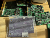
Huge thanks to @xodaraP for sending this Anzac care package of goodness - there is way, way more, this is like 1/4 of it.
With this enormous stash of NeoGeo spares I'm now ready to complete all my half done repairs. AND build my own AES for only 4x what it would cost to buy a tested fully working one
With this enormous stash of NeoGeo spares I'm now ready to complete all my half done repairs. AND build my own AES for only 4x what it would cost to buy a tested fully working one
Attachments
Last edited:
Most of the BOM is reasonably straightforward, except for all the bits that are unobtanium and need to be salvaged from an existing board of course.
I dimly, vaguely remembered some research I did ages ago in to the DIN-8 connector. This is now obsolete and mini-din-8 is often sold as din-8 for added confusion.
There were two versions of DIN-8 and they weren't compatible - SNK used the 270 degree version, and Sega used the 262 degree version, and there was also a 260 degree version. And all of them had different landing patterns for the THT pins.
262 (not what we want)
https://console5.com/store/din-8-fe...sega-genesis-mega-drive-master-system-av.html
https://console5.com/store/din-8-female-socket-pcb-through-hole-u-style-262-10mm-ground-spacing.html
270 (yes what we want)
https://console5.com/store/din-8-pi...t-emi-shielded-and-a-v-rated-c-style-270.html
https://www.aliexpress.com/item/1005002331748706.html
I see that the board devs kindly put in both the 5mm and 10mm spacing for those front two ground pins - thanks guys!
Ouch! These guys are really expensive, and the BOM calls for 50+ of them!
https://nz.mouser.com/ProductDetail/KEMET/B-06-R-25?qs=gt1LBUVyoHn1EGcP7DmcpA==
Anyone got an alternative supplier?
https://nz.mouser.com/ProductDetail/KEMET/B-06-R-25?qs=gt1LBUVyoHn1EGcP7DmcpA==
Anyone got an alternative supplier?
