What's new

adgenet

Professional
Joined
Feb 27, 2019
Messages
199
Reaction score
199
Location
SF Bay Area
I picked up a super cheap MV1B a while ago and never tested it. I pulled it out today and it seems that it has a strange color issue.
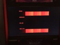
Red is all blown out, and there are traces of red in the white color bar (no cartridge, unibios test). This color problem appears in-game as well when a cartridge is inserted.
The diag rom tests all pass no problem.
I saw a thread somewhere that mentioned resistors for the video dac, but I checked these and they seemed ok, although they're too tiny to read where each of the correct values should be, the values seemed to be the normal and match https://wiki.neogeodev.org/index.php?title=Video_DAC.
How else can I troubleshoot this?

image1.jpg
 
Last edited:
I did some fiddling around with the board, and desoldered both U6 and U7 LS273F ICs.
Swapping one of them to the other position caused a whole screen blue tint. Then, swapping back, now I get a red tinted screen. Seems green is missing completely.
Running the board with one of the LS273s in the U6 and U7 position ends up with the blue tint or red tint but still seeing the problem with the white bar.
Sample red tint:
IMG_1150.JPG

Switching to the other LS273 and doing the same thing results in a totally black screen though.
I have a feeling one of these LS273s is dead completely (maybe the desoldering heat killed it for good?) and the other is only partially functioning (where did green go? why is white still messed up?)

Am I on the right track?
Do I need to locate an identical Fairchild LS273SJ or can I just get any LS273 from a supplier?
Will this work? https://www.digikey.com/product-detail/en/texas-instruments/SN74LS273NSR/296-31856-1-ND/3505253
Is it worth messing with the LS05 right next to these as well?
IMG_1152.JPG
 
you can use any 74LS273 in that package style.
be carefull about that - there are 2 sizes of soic package with 20pins - one is wider and and old japanese standard.
 
Replaced both LS273 ICs and the LS05 with brand new ones, didn't solve it.
Back to square one with the same picture as in the first post (All colors present, red is blown out, and white has red in it)
There are scratched traces on the bottom of the board but continuity tests check out ok on all that I could find.
I also checked and reflowed the big NEO-GRC2-F chip which looked a little crusty, but that had no effect.
What else can I check?
 
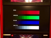
Fixed:
image1.jpeg

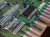
Turns out there were two pins on NEO-GRC2-F bridged together somehow. These two pins run to one of the LS273s.
There were no visual indications of a short using a 16x loupe to go over everything, but doing a continuity test revealed the short.
I reflowed the offending connection again on the GRC2, but for much longer, and with a higher temperature. This appears to have fixed it.
Out of curiosity, I put the original LS05 back, and this also worked. I then removed and replaced one of the LS273s with the original, which caused a tinted screen. I suspect that one of the original LS273s is in fact bad so I put both of my new ones back on the board.

As a side note, there is disgusting brown, old, probably factory flux that boils out when you reflow the big ICs on my board. I wonder if this flux had a hand in the fault? Can't really think of a good way to clean it up without a hot air station and removing the chip from the board though...

Also a PSA:
If you have a chip programmer, it most likely has a logic chip test function. This will remove any doubt that your 74LSwhatevers are good or bad. Don't be like me and slack on buying smd adapters for it. They're a couple of bucks at most! I really wish I had one for this troubleshooting job.
Pick up a set of adapters so that you're all set in when you come across a board (like this MV1B!) that uses smd logic chips that needs troubleshooting so that you aren't stuck just blindly replacing them.
 
neo boards are cleaned at the factory, yours has probably been re-soldered in the past.

btw, the most usefull programming adapter is the 28pin soic one - great for those damned srams!
 
Thanks so much for sharing this @adgenet
I am experiencing something very similar with my mvs1b but I am missing blue.

I too replaced the ls05, and the LS273s to no avail.

I did see some bridging on the GRC2
And I fixed it thanks to your post here but, dang…. I am still without blue.
I can’t seem to find a ls273 to grc2 schematic. Do you know where you found yours? I want to do a quick continuity test as my video DAC looks fine and the resistors are all within spec

Thanks if you can help.
I’d love to see if I need to Relace any smd caps or resistors (had a few off but not a lot)
 
Back
Top