What's new

xodaraP

Legendary
Joined
Sep 21, 2016
Messages
4,751
Reaction score
3,794
Location
Gold Coast, Australia
Hi guys,

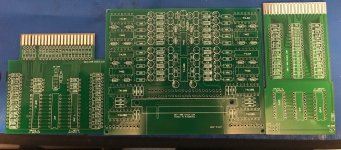
I would like to get some reference cards made up for my HP logic comparator, HP offers the schematics in the manual but I wouldn't even know where to start with the PCB design software so I'm hoping someone else might be able to make up the files I need to order the boards. Better yet - someone may have already made up the files and ordered some and hopefully I can persuade them to let me use the files to order some myself :P
 
Necro-bumping this because I'm trying to figure out how to set up a new reference card. The instructions are ok except I'm unclear on what I'm supposed to drill. I know it's the output pins but where do I drill on the pcb? Anyone?

For those who want to make some more reference card blanks here is where you can download the gerbers: http://www.jammarcade.net/hp-10529a-reference-card-gerbers/
 
You drill out the pad ON THE BOTTOM where the output pin connects to to break the connection to the edge connector

You don't drill all the way through, just enough to destroy the pad on the top side.

Example given where odd number pins are outputs

A8CF2C7C-806D-42E2-B941-076F68136DC2.jpeg
 
Gotcha. Thanks.

The 20-pin version of the comparator the guy on KLOV was developing turned out to be a bust, huh?
 
Yeah, he did actually make a few of the PCBs (I managed to get one) - but it still can't do most 20 pin stuff like buffers/line drivers :(

It's a shame he didn't make more anyway just because 10529a units are getting harder and more expensive to get (although the DIY version isn't going to be cheap to assemble either)

I got the PCB regardless and plan on building it just so I have a spare comparator. I'm also hoping to get a reproduction of the self test board for my 10529a

I also got his repro of the universal card I need to build at some point as well.

It would be awesome if he'd sell or release the Gerbers but I can see his point given the time spent on designing it.
 
Luckily mine was NOS and came with the self-test, universal, and 10 blank reference cards.

I'd redo the design of his pcb using mostly SMD componenets to make it a bit easier to assemble and maybe a bit smaller.
 
Nice work. I'd love to see the self test card repro'd if you ever find yourself interested in doing it :P
 
You are sure that you drill the pad on top?

The instructions on KLOV seem to indicate you drill the bottom. Confusing.
 
Let me get one I've made previously to confirm......

I thought the bottom was just power/ground lines
 
My apologies, it is the bottom side of the via you drill out (makes sense since that's where the numbers are)
 
Gotcha. Thanks.

The 20-pin version of the comparator the guy on KLOV was developing turned out to be a bust, huh?
I ordered a set of his PCBs off of him a few months ago. AFAIK he should have more.

I have all the materials on hand to assemble a complete unit-just haven’t found the time yet to do so.

6ABE1708-5142-4D8E-8219-13FC6CE82AAA.jpeg
 
You are sure that you drill the pad on top?

The instructions on KLOV seem to indicate you drill the bottom. Confusing.
Bottom line is, make sure the output pins don't connect to the edge connector on the bottom and leave them connected to the edge connector on the top.
 
The diodes seem to be the most difficult part to find
Do you mean the 1n5226B diodes marked on the main comparator board?
How did this device turn out once you built it?
I don't suppose you have a BOM for the device or the test cards as there's a few components not marked on the silkscreens?
 
Back
Top