What's new
@Zebra The code should work on a Leonardo as well! You’ll have to try it and tell me how it goes as I haven’t actually tested it out.

The reason it only works on some Arduinos is because the processor needs to support a special ability that allows it to pretend to be a USB peripheral. Only some of the processors in the Arduinos support this.
OK good. That means it should work as the Leonardo was what they used to demonstrate the Arduino analog joystick mouse on YouTube.

If I understand what I'm reading correctly, I should then be able to use it with the Titan One or Titan Two device to use the Arduino on other platforms. It seems to output like a "standard" HID device (if there is such a thing). The Titan software will apparently capture the USB traffic between peripheral and PC, then map that traffic to specific commands in the PS3 or Xbox 360 protocol etc.
 
Honestly learning to code for something like Arduino is very easy. it's far less complex than trying to write a program for a computer. and honestly it's a good universal language that gives a good foundation for other platforms.

Here's a good tutorial for people who don't know anything about code at all: https://www.programmingelectronics.com/tutorial-3-arduino-ide-and-sketch-overview/

The best way to learn things like this is to have a project in mind and start by learning what you need to get the project done.

It can be easy to look at a project and feel overwhelmed, but just break it down into tiny little parts and then break those parts down into even smaller parts and tackle each part one at a time.
Thanks, I'll take a look. If it's something that can be learnt quickly then it may be possible for me. My main limitation is time. Most of my "free" time is currently taken up with learning how to use my new CNC mill.

Sometimes it feels like we just don't live long enough to learn all the things we want to know....

I guess I should factor in the eventual time saving from being able to do what I need to do without having to search the whole internet for the one guy that did it already.
 
I've been doing a little testing (aka playing) recently to try and figure out how Sega IR guns work (I can't live with not knowing). A guy on the other forum claimed they determine coordinates by calculating the angles between the IR LEDs (and the gun). I think that would be impossible with type 2 hardware unless I missed something key? What do you guys think? And, has the gun sense IC ever been dumped so we could see the code?

I don't know anything for sure yet but you can aim at any given point on screen from a literally infinite number of angles. For example, I can aim at the center from the left or right. I can turn the gun on it's side etc without harming accuracy as shown below:

https://www.youtube.com/watch?v=Hrd90Hr9AMk

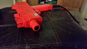
There is no tilt sensor in the standard Sega IR gun and there is nowhere to tell the gun sense board how big the screen is. The angles between each led would change if the screen was larger or even if you just stood further back. It seems like a lot to calculate on the fly with nothing but a photo diode to see with. plus, the guns seem to be designed to restrict the view to what's directly in front. The IR shield sits in an opaque tube with only the tip visible:


As I understand it, a photo diode converts light to voltage. They can measure if there is light in front of them and use the varying voltage response to judge intensity or color. Or with an additional processor (like a gun sense board) they can use that info in conjunction with timings to determine position (like on a crt light gun). I.e. The sensor tells it if I'm pointing towards an IR light source, the timing tells it which of the ten led boards it is. The intensity tells it how far I am from the closest LEDs.

Some say the mechanism to know which led board you are pointing at is done with timing by lighting each led individually in a circular sequence. I can buy that if it's modeled after crt light guns. It's no stretch that the brief could have been "here's a light gun, make me one that works on any screen". Another potential option would be varying voltage (e.g. Progressively less or more for each led) or different wavelengths to generate a different voltage response for each led etc. if you can vary the light intensity, you'd get different voltage responses from the photo diode from each led board. just a thought.

If you think of the LED boards as being five sets of two instead of one set of ten, you can start to see how it might work. e.g. If I point at led board 1, I get a 5v response. As I move my aim across to led 2, the voltage gradually reduces until I get half way between them when it starts increasing again until I'm pointing directly at led 2. Not entirely different to a pair of 5/channel IR line followers except with one moving sensor instead of one for each led.

I'm thinking I may be able to capture some of the voltage response info from the mystery pins on the gun sensor module. They have to do something and the voltage response from the photo diode has to travel through at least one of them.
 
The gun effectively has a camera in it that can only see IR (Infrared) light.
Does this look like a camera to you?
View attachment 28835
I realise that its some sort of PIR type sensor, but it must produce some sort of pixel map right?

Feel free to completely correct me if I'm wrong, but in essense it must be doing something like what I've said - I can't see that its at all possible if that was a photo diode.
 
I beleive people think its a PIR sensor that its somehow using as a camera.
It's a PIR sensor (4 of them actually), it says as much in the patent documentation on this system, and it's not being used as a camera, it's being used as a PIR sensor. There's no pixel map, it simply detect intensity of the LEDs relative to the quadrants of the IR sensor. it's the same exact mechanism as a IR motion sensor on an old alarm system.
I beleive there is an FPGA on the gun I/O board, or some other sort of CPLD.
There isn't
old_gun_sense-1200x900.jpg

it's got an EEPROM and a NEC CPU and the rest is basic 74 series logic or analog ICs.
newer boards simply use an SMD version of the NEC CPU with the code embedded.
 
@twistedsymphony Ah fair enough, my bad. Can you explain how it works then?

Also do you happen to have a link to the patent document, would be an interesting read?
 
I have many times before. most recently in my write up here: http://solid-orange.com/1611

which is linked on the first page of this thread and on at least 3 other posts :P

@rtw has recently done some testing using a scope to look at the data on the various pins.

LED chain is confirmed to be a simple addressable set of LEDs it's basically just got a flip-flop to turn them on one at a time from a simple pluse signal.

more research needs to be done on the actual data coming off of the sensor but it's essentially analog data which backs up the little technical info that could be gleaned from the patent about it using IR region/motion/intensity to determine position.
 
Last edited:
Thank you - I've seen your write up before, it's really interesting but the lowest level of details you goto is: The Gun Sense board illuminates the addressable LEDs one at a time and takes an IR intensity reading from each quadrant of the sensor in the gun. Because it knows the position of each LED and the intensity of each quadrant for each LED it’s able to determine where the gun is being pointed with very good accuracy.

Do we know how the math actually functions to go from a effectively a 2x2 intensity camera (if I understand how the PIR functions) to a pixelmap of where it's pointing? The PIR plates would have to be calibrated mentally well for it to detect a light intensity change of such as small value - but maybe thats what the POTs are for on the PCB? I'm also assuming that A B C and D connections (from your write up) would be the voltages from each PIR plate?
 
The sensor in the gun is flat photo diode. These are generic and just have to match (ir sensitivity and voltage response) to the led intensity and required voltage output. on their own, they provide two bits of info. Is there light opposite? And how much? The info is expressed as voltage. It's incredibly simple.

After researching similar tech I am fairly confident that it is a modified variant of an IR gesture sensor. This tech has been written up and explained extensively in docs like this:

https://www.osapublishing.org/oe/fulltext.cfm?uri=oe-21-8-9206&id=252485

And this:

https://www.researchgate.net/public...erties_of_an_Active_Linear_Gesture_Sensor#pf3

If you skim over them you'll see fairly quickly where it's similar and how it differs. I.e. Instead of capturing reflected light with photo diodes mounted next to LEDs, this system uses one photo diode cluster pointing directly at the IR light source (for extra range and greater precision).

The process of using a pulsed pattern for the photo diode to distinguish between LEDs is also explained in those docs. It's nothing unique apparently.

Given what they say about the problem of the overlapping "ambiguous zone", my guess is that they use an analog voltage output to make use of the ambiguous zones. I.e. Using the rising voltage response from one led and the reducing voltage from it's neighbor to determine directionality of movement and positioning data between two LEDs. e.g. If it's getting 2.5v off LED 3 and 2.5v off LED 4, it knows it's exactly in the middle of those two on the X axis. it then does the same with the LED below for the Y position. This also explains why they use ten led boards instead of two and why the photo diode is mounted inside a long opaque tube which limits it's view.

On previous issues with capturing data off the Sega gun sensor. It's possible people were trying to be too clever (by thinking of it as data) Perhaps the relevant info at that point in the circuit is simply voltage and frequency. We need a scope on this.
 
Do we know how the math actually functions to go from a effectively a 2x2 intensity camera (if I understand how the PIR functions) to a pixelmap of where it's pointing? The PIR plates would have to be calibrated mentally well for it to detect a light intensity change of such as small value - but maybe thats what the POTs are for on the PCB? I'm also assuming that A B C and D connections (from your write up) would be the voltages from each PIR plate?
I left out any "speculative" details in my write up. but from what I've been told they are indeed calibrated on tight margins from the factory. even minor tweaks of any of those pots in the sensor module can cause it to not function. I also from what I understand OHMIC wasn't ever even willing to explain to Sega the math behind how it works. So until someone reverse engineers it, we wont know.

I would think analyzing the EPROM code and putting a logic analyzer on the LEDs and sensor outputs at the the same time while pointing at certain points of the screen would be the best place to start, but I don't have the tools for that.

EDIT: @Zebra, YES that's exactly the technology I was referring to with the IR based Alarm System motion sensors.
it's basically just a more tightly calibrated version of one of these:
wired-pir-motion-detector-sensor-for-home.jpg


it's all the same principal technology, but the alarm sensor is designed to detect ir changes across a large area, the gesture setup is designed to detect it over a small area, and gun setup is simply designed to detect it with greater accuracy.
 
Last edited:
I have many times before. most recently in my write up here: http://solid-orange.com/1611

which is linked on the first page of this thread and on at least 3 other posts :P

@rtw has recently done some testing using a scope to look at the data on the various pins.

LED chain is confirmed to be a simple addressable set of LEDs it's basically just got a flip-flop to turn them on one at a time from a simple pluse signal.

more research needs to be done on the actual data coming off of the sensor but it's essentially analog data which backs up the little technical info that could be gleaned from the patent about it using IR region/motion/intensity to determine position.
Lol. I'm starting to feel your pain on this. No matter how many times you explain that Sega and Namco guns don't use a camera and aren't the same as Raw Thrills guns or Wii remotes, it is apparently impossible for this info to sink in and get processed for a percentage of the population.

After you explain someone always feels the need to say, "oh, so it's basically a Wii remote".

I had to stop myself getting into an argument over on arcade controls on this. I'd tried to help one of the diy projects by sharing what I learnt about my new guns and some guy was sending supposedly smart people down a dark rabbit hole. He convinced them it was a camera capturing angles and using elaborate algorithms to calculate coordinates. I decided it was best to write off that project and all involved at that point. They're probably still looking for a "trig expert".

Anyway, I gave up murder as one of my new year's resolutions. It's going well so far besides a few slip-ups...
 
Maybe it's just my devious mind and general lack of faith in human character (or talent) but often, when someone won't tell you how something works, it's because they are worried or ashamed by how simple and easy it is to copy VS how much they are charging and how little original work is involved. We know the basic tech is already public domain stuff.

If the set-up really relied on software code so complex it was beyond even Sega's capabilities to do themselves (or reverse engineer), that software would be copyright protected. Software protection lasts a really long time.

My guess is that it's Sega that doesn't want to share as ripping off arcade owners with outrageous markups on low quality parts is their business model. You need the mystic to charge $250 for a $6 photodiode.

My guess is that we'll laugh at it's simplicity when we finally access the code. Has anyone checked the HOD2 CHD in mame to see if the Gun sense IC is there? It's certainly mentioned in the mame research info online as if it is.
 
@Zebra thanks for your info on the guns much appreciated.

All the dumped images from the gun boards are in hotd2 BIOS in MAME.
The CPU that these gun boards is running on is not exactly a powerhorse :)

Code:
/*
 Gun board info:
 "838-13143-nn IC BD GUN SENSE xxx" board, D78213 MCU based, was used in big number of Model2 / Model3 / NAOMI / Chihiro / Lindbergh games.
 known firmwares:
 EPR-20006A  oldest revision?
 EPR-21262 - older revision, used in: 04 HOD (House of the Dead), 06 JPT (Jurassic Park The Lost World).
 TG12      - newer revision, used in: 08 SPY, 09 SPY UR, 11 SPY UR EXTRA - Confidential Mission and later games, backward compatible with older games as well.
*/
 
@twistedsymphony I’ve removed my posts with the incorrect info, feel free to remove your replies if you want to make the thread shorter - thank you for the corrections.

What seems strange to me is that it requires 5 LEDs to for detecting the X Axis but effectively only 2 LEDs for the Y axis. I know the Y axis is shorter but at a rate of 4:3 or 16:9 not 5:1.
 
What seems strange to me is that it requires 5 LEDs to for detecting the X Axis but effectively only 2 LEDs for the Y axis. I know the Y axis is shorter but at a rate of 4:3 or 16:9 not 5:1.
that's because it doesn't use all 5 to determine X position. it only needs 2. so when you're points at the left side of the screen it doesn't even see the LEDs on the right and it uses the left two most LEDs to determine position.

if you look at the technical information on the OHMIC site you can see that the technology is designed to work with only 4 LEDs, one in each corner.

you can think of it like it breaks the screen up into 5 smaller screens and then determines the position within each of those screens.
 
I understand that - what I mean is why is 2 points of reference at the extremes suitable for the Y but not for the X when the width of the screen isn’t a factor of 5 bigger than the height. I’d understand 3 or maybe 4 LEDs but 5 seems a lot.

They took away 2 LEDs from the Height perspective from jpark to hotd, I wonder why they didn’t also remove an LED from the width perspective as the half height gap they’ve just removed is far larger than say removing 1 LED from the width gap.
 
just pure speculation on my part but it's probably because of the way most players stand with the gun near the center of the screen vertically, but with wildly different positions horizontally depending on where the player is standing.

honestly these kinds of things are mostly just determined by testing. you try it with 4, not enough, bump it up to 6, not enough, try 10, etc.
 
I understand that - what I mean is why is 2 points of reference at the extremes suitable for the Y but not for the X when the width of the screen isn’t a factor of 5 bigger than the height. I’d understand 3 or maybe 4 LEDs but 5 seems a lot.

They took away 2 LEDs from the Height perspective from jpark to hotd, I wonder why they didn’t also remove an LED from the width perspective as the half height gap they’ve just removed is far larger than say removing 1 LED from the width gap.
The system is slightly less accurate on the Y axis than the X. The reason for the reduced number on the Y is fairly obvious though. You wouldn't want to mount LEDs covering the screen. Having additional LEDs for Jurassic Park may have slightly improved accuracy at the edges but the sensor would not see them from the center where most the action happens.

We also know, from the gesture sensor info, that photodiodes struggle with an "ambiguous zone" when picking up light from too many different LEDs at the same time. They are dumb and blind devices that can only distinguish one led from another buy lighting them individually in a circular pattern. Imagine how much harder it would be if that led pattern had to travel up and down as well as round and round. It would confuse X and Y motion or misinterpret diagonal motion.

Breaking it down into five sets of two is smart. Systems that use just one or two LED clusters like the Guncon 3 or the cheap Chinese IR sensor PC light guns on Aliexpress, are usually fairly accurate in the center or close to the LEDs. They start to fall down and get out of alignment towards the edges. It was probably also helpful for development by giving them distinct zones that could individually calibrated to give it the best chance of crosshairs lining up with iron sights across the whole screen. It's like squeezing a bump out of a balloon or playing Whack a Mole trying to calibrate other IR guns.
 
Check out this patent info for the use of very similar technology for use with some kind of more precise touchscreen / X Y positioning pointing system.


https://patentswarm.com/patents/US7705835B2

It's very poorly written and not an easy read, plus it flip flops between different methods which are not all relevant to this but... where it is relevant, it has both methodology and pseudo code describing how it works.

It's actually fairly simple once you get through the appalling writing and unnecessary use of jargon. I had a few "ah ha moments" from the little I skimmed through. I found it because I was curious if you can hack an IR touchscreen to use a photodiode as a remote pointer instead of physically touching the screen.
 
Back
Top