What's new

Supergun VEGA 9000 DX reproduction PCB CH-11A internal management JAMMA Help!!!!!

chacal231077

Grand Master
Joined
Dec 21, 2017
Messages
860
Reaction score
359
Location
France
Hi! :)

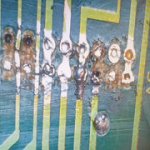
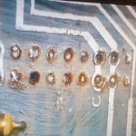
I did some big shit on a PCB which manages the Jamma on a VEGA 9000 DX;(


I wanted to unsolder the connector like this because it was originally an Omron XG4A-4031 which was broken.


But with the quality of the tin used it made shit :cursing:I can not unsolder, flux, desoldering gun ect ... impossible I damaged everything pads and on the tracks ;(

70667487.jpg


800px-VEGA9000DXIN2.jpg


;(
20211217-132344.jpg
20211217-132805.jpg
20211217-132759.jpg
20211217-132433.jpg
20211217-132424.jpg
20211217-132415.jpg
20211217-132408.jpg
20211217-132401.jpg
20211217-132350.jpg


https://i.ibb.co/j3wRbxX/20211217-132344.jpg
https://i.ibb.co/GC0zW8f/20211217-132805.jpg
https://i.ibb.co/ncFVxtx/20211217-132759.jpg
https://i.ibb.co/6tv3Vr6/20211217-132433.jpg
https://i.ibb.co/Y84NrHQ/20211217-132424.jpg
https://i.ibb.co/gzV3MmH/20211217-132415.jpg
https://i.ibb.co/SBm4MQQ/20211217-132408.jpg
https://i.ibb.co/bJfggD1/20211217-132401.jpg
https://i.ibb.co/WGyyDL4/20211217-132350.jpg


I would like to know if someone would be able to make a repro or a plot on Printed Circuit Board Design Software if you have the time: D I do not know used this type of software pity.


I can give the dimensions of the PCB if necessary

Thanks for your help help :thumbup:
 

Attachments

  • 20211217-132350.jpg
    20211217-132350.jpg
    18.2 KB · Views: 95
  • 20211217-132401.jpg
    20211217-132401.jpg
    20.6 KB · Views: 97
  • 20211217-132408.jpg
    20211217-132408.jpg
    19.4 KB · Views: 88
  • 20211217-132415.jpg
    20211217-132415.jpg
    18.9 KB · Views: 88
  • 20211217-132424.jpg
    20211217-132424.jpg
    15.2 KB · Views: 86
  • 20211217-132433.jpg
    20211217-132433.jpg
    14.6 KB · Views: 104
  • 20211217-132759.jpg
    20211217-132759.jpg
    17 KB · Views: 81
  • 20211217-132805.jpg
    20211217-132805.jpg
    17.4 KB · Views: 101
  • 20211217-132344.jpg
    20211217-132344.jpg
    18.1 KB · Views: 88
  • 20211217-132350.jpg
    20211217-132350.jpg
    18.2 KB · Views: 91
  • 20211217-132401.jpg
    20211217-132401.jpg
    20.6 KB · Views: 97
  • 20211217-132408.jpg
    20211217-132408.jpg
    19.4 KB · Views: 92
  • 20211217-132415.jpg
    20211217-132415.jpg
    18.9 KB · Views: 97
  • 20211217-132424.jpg
    20211217-132424.jpg
    15.2 KB · Views: 88
  • 20211217-132433.jpg
    20211217-132433.jpg
    14.6 KB · Views: 111
  • 20211217-132759.jpg
    20211217-132759.jpg
    17 KB · Views: 80
  • 20211217-132805.jpg
    20211217-132805.jpg
    17.4 KB · Views: 80
  • 20211217-132344.jpg
    20211217-132344.jpg
    18.1 KB · Views: 80
Last edited:
If it's just a two-sided PCB it should be straightforward to copy. I can probably do it if you don't get any other offers but I'd probably ask you to loan me the broken PCB as it's easier to have it physically in front of me.
 
ok Thank you bodgit :thumbup: yes no problem lending it to you

if someone could take a picture of the PCB of their Vega 9000 DX on the solder side, because there are pads that communicate with each other, and on mine we don't see them anymore

Thank you :thumbup:
 
I found this page on Arcade Otaku: https://wiki.arcadeotaku.com/w/Vega_9000_DX

There are four manual pages right at the bottom that have the pinouts of the various connectors so it should hopefully be obvious which pins should and shouldn't be connected, but a decent picture of the underside can't hurt.

yes I know this page :thumbup:

I would add the different components to complete its wiki capacitor ect. :)
Yes a picture below would be welcome :saint:
 
If I were you I would take the opportunity to modernize it. Because the rear connector is a 56 pin jamma connector for example you can just remove all that stuff and bolt in a minigun or a HAS and be done with it. Superguns have come a long way since this one was made back in the 90's. All this one does for the RGB lines is add 100 ohm resistors on the RGB lines and nothing to the sync line. There's no point putting the time in to reproduce something that's not best practice anymore.

I love the VEGA control box and I use mine every day but I don't run any of my video through it anymore. I was too lazy to modify the internals of mine and I just made a harness like this:

1639778450287.png


If you desparately want to keep it original, that board doesn't look too rough to draw up in KiCad someone would just need to put the time in.

Seems weird that you can't desolder it though, are you adding leaded solder before trying to desolder? Are you using enough heat? Seems to me like it should be a pretty straight forward job - even with what you have there it looks repairable to me.
 
I would like to know if someone would be able to make a repro or a plot on Printed Circuit Board Design Software if you have the time: D I do not know used this type of software pity.

I learned KiCad from a free udemy course a few years back, it was a pretty fun thing to do. If you have the time it's a worthwhile skill so you can make little bits and pieces for modding your stuff. This would be an ideal project to learn IMO.
 
If I were you I would take the opportunity to modernize it. Because the rear connector is a 56 pin jamma connector for example you can just remove all that stuff and bolt in a minigun or a HAS and be done with it. Superguns have come a long way since this one was made back in the 90's. All this one does for the RGB lines is add 100 ohm resistors on the RGB lines and nothing to the sync line. There's no point putting the time in to reproduce something that's not best practice anymore.

I love the VEGA control box and I use mine every day but I don't run any of my video through it anymore. I was too lazy to modify the internals of mine and I just made a harness like this:

1639778450287.png


If you desparately want to keep it original, that board doesn't look too rough to draw up in KiCad someone would just need to put the time in.

Seems weird that you can't desolder it though, are you adding leaded solder before trying to desolder? Are you using enough heat? Seems to me like it should be a pretty straight forward job - even with what you have there it looks repairable to me.
yes good idea to make an evolve version

A version which manages a pinout of today with the + 3.3V and a seventh button.

vewlix_s.png

Already this type of version and already not bad.

if somebody participate thank you
 
Hi! :)

Here is the news since my request.

I already thank Bodgi for working on it despite the condition of the PCB he received, and I thank him deeply.


vega9000dx-jpg.172872


As he explained to me that it was not 100% functional and with his agreement, I put the files of his work.


Here is the result of my test :

Well in fact I only have the 2 Player which works, the 1 Player the LEDs of the turbo switches of the buttons do not work. and I have +7V instead of +5V on the 1 Player buttons.

I did not connect a PCB to it because the famous +7v could cause possible damage to the input on the PCB.

The LEDs on the audio/video PCB are active.

On the PCB that I had manufactured by JLPCB, they are missing on the tracks the removal of the protective varnish on the track, Ground, +5V, -5V, +12V to be able to solder the cables.


A small track extension is also missing on the 1k resistor where there is a +Led marker, a pad is missing to solder the wire.

but I think that putting a little connector for each voltage cable would be much more practical, the same for the +Led and - Led wire


If anyone has a Vega 9000 DX to compare and correct errors I thank them in advance. :thumbup:
 

Attachments

Last edited:
Hi! :)

I'm looking for someone who could take a good photo of the bottom of their PCB so I can compare it and find the connection problem with the first player.

Thanks.🙏:thumbup:
 
Back
Top