What's new

hatmoose

Champion
Joined
Mar 25, 2021
Messages
1,094
Reaction score
2,280
Location
New Zealand
I've been putting this project off for ages - but the thought of putting all this stuff away again has finally spured me into action

The Mighty Sony E1E was the finest 240p monitor ever made - 1000TVL has never been rivaled. Some say the "E" is for Evaluation, some say it means Extrodinary, I say it means Enormous

I bought this guy for fifty kiwi pesos about 12 months ago, before PVM/BVM prices went insane in this country, even then $NZ50 (about $US30) was an amazingly good price. Because it had been dropped.

If you have ever wondered what a busted shadow mask from impact damage looks like... it looks like this. This particular tube also has 140,000 hours on it - this is not a joke, 140,000 is a lot of hours. I'm actually not even sure how they managed to run the thing for 140,000 hours - there are only 9000 hours in a year and this was made in 1995... Anyhoo even if it wasnt destroyed this tube is long past its lifespan.
View attachment 80659

So I found a suitable tube-donor as a replacement, a Sony PVM-20M4. This one had been through several pairs of incompetent hands attempting to repair it before it came to me. It was sold as "suitable for tube swap only". I think i paid about $NZ100 this this. Every single other part of this monitor has problems, the chassis is twisted, the power supply is dead, the A board is dead, it is absolutely knackered. But the tube seems to be in good condition - so swap them I shall.

Here they are side by side
View attachment 80658

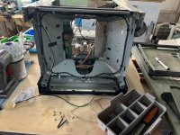
And here is the BVM 20E1E starting disassembly
View attachment 80656

So the major challenges that i see with this are
1) The Chassis on the BVM is twisted from the drop, I'll have to true it up somehow
2) The front bezel is all smashed up, will need to repair with some kind of glue
2.5) There is no 4:3 mask, will need to model and 3D print that
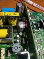
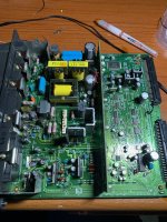
3) the controller (BKM 10R) was damaged in the drop, will need to fix that
4) although the tube is a drop-in replacement the yoke and the convergence rings are NOT. Normally these were matched and tuned at the factory by an experenced craftsman. In my case they will be bodged in my garage by a drunk munter. ings

These are (were?) two very nice monitors, total cost was less than $100, potential benefit is a working BVM-20E1E. So the stakes are low and the prize is high

If anyone has any thoughts/experence/tips with this sort of thing I would love all the help I can get.
 
Good luck! I've done something similar and did a write-up here

Interested to see how you go printing up a 4:3 mask, I have a BVM that is missing that piece too, would buy one if you come up with something good!
 
Solid progress on pulling stuff apart, now just the minor matter of putting it back together :)

In order to extract the tube from a PVM you need to dismantle the entire thing. Boards and power supplies gone
3F77B786-0E68-40A5-A516-1EB34A1548E3.jpeg
Every other bit gone Until finally
6A6F7D9C-D827-4144-AC4D-761B1EDF451E.jpeg

Well, at least the spares bin will be well stocked. Shame none of it works…
48C488D5-527A-4A5A-A4D5-8C2B3068355F.jpeg

The BVM on the other hand, remove the neckboard, unplug 5 cables, undo the bolts at the front. tube lifts right out - maybe 3 minutes start to finish

4B0B2D68-9E4E-4D7F-8A11-23BBF848BD79.jpeg
Looks kinda trippy with the drier in the background
EA6854F8-5098-429C-B10E-015B60AB3C22.jpeg

Now I have the fun job of twisting the frame back into true.
 
Really, really pleased with the way the chassis came out - it's hard to see in this photo, but it was comicly awful before - like something Wile E coyote would try and drop on roadrunner
IMG_2825.jpeg
After much pounding everyhting now sits flush, the panels all line up nicely and it looks like a sensible thing again
IMG_9805.jpeg

Next step from there is to repair the Bezel and line up all the cleats so the tube can sit straight.

For the Bezel I'll be trying a variety of glues and compounds to see what works best - will use the discarded carcass of the 20M4 for testing.
IMG_9787.jpegIMG_9786.jpeg

The last of the chassis repair needs parts, will get onto that tomorrow
 
Straightening up the cleats turned out to be an enormous pain in the ass. Eventually I had to drill the old rivets to get them out, then pound the cleats back into shape, then rivet them back in. Turned out pretty well in the end, but took a few hours to get them all perfect with hand tools.
IMG_9807.jpegIMG_9808.jpeg

For the bezel I decided to use a combon of plastic model glue, to tack it into place, then epoxy putty to strengethen it up. Luckily the back of the bezel it hollow so can pack plenty in there.
IMG_9838.jpeg

The controller was a Sony BKM-10R - there are actually some cool open source projects to re-create these. The existing one worked (barely) and was absolutely filthy. The knobs had been smashed off the front and the encoders were damaged.
IMG_9825.jpeg

Initally my plan was to replace the encoders with new ones, but this turned out to be harder than expected due to the odd form factor.
16 x 18mm package, 3 pin at 5mm centres, 6mm shaft diameter, 14mm shaft length, 24 position, 0 detents
So I gave up on that and rebuilt the existing ones whch was also quite time consuming. I tried a few things to get the faceplate clean, in the end I washed it with warm water and soap which to my surprise worked really well, came out sparkling
IMG_9836.jpeg

Net result, one fully working and great looking BKM-10R
IMG_9840.jpeg

I fitted the RF shield back into the (now square) chassis, and test fitted the old tube back into the chassis just to make sure it WAS square. Learned a valuable lesson doing this - the neck of the tube sticks out further than you think! Just a very slight knock but enough to teach me the lesson.

Perfect!
IMG_9839.jpeg

Tomorrow I hope to complete the bezel, check that everything works as expected with the old tube, then swap in the new tube.
 

Attachments

  • IMG_9821.jpeg
    IMG_9821.jpeg
    214.7 KB · Views: 121
Sometimes a product comes into my life that is so perfect that I get upset that I didnt discover it before - in this case epoxy plastic putty.

Goes in squidgey, sticks like you would not believe, sets absurdly strong.

My pro tip is use a q-tip to shape it; It sticks to pretty much everything but q-tips, by using them you can ram the putty into those corners real good. I used it to re-attach this screw post on a damaged CPS2 A board shell for practise - it's now so strong that i cant snap it off with pliers
IMG_9864.jpeg

Bezel is now re-assembled as much as possible -it looks OK from the front, most of the remaining damage will be hidden by the new 4:3 mask that I'll get to work on designing one day.
IMG_9867.jpegIMG_9868.jpeg

So that really just leaves the minor matter of the busted tube. There are two problems
1) Classic rainbow from a detached shadow mask - this can sometimes also be caused if the yoke has shifted, but as you can see from the photos its much too regular for that
2) weird zebra patterns - I have never seen this or heard of it before - I'm really hoping that its damage to the tube, because if it's anything else I'm stumped

IMG_9870.jpegIMG_9871.jpeg

Also a video of the weird zebra pattern on the tube - any thoughts do please let me know
 

Attachments

  • IMG_9874.jpeg
    IMG_9874.jpeg
    210.7 KB · Views: 101
  • IMG_9873.jpeg
    IMG_9873.jpeg
    284.8 KB · Views: 102
Getting close now.

Tube swap = done!
59D699D7-F8D4-4D28-8E3E-8A04B4AC7B45.jpeg

The new tube made an enormous difference, colors are much better. But then the old one had 100k+ hours on it so no surprise there.
0AE41C04-2FC3-44C3-A101-BAA6CE00D317.jpeg

Still some alignment/convergence/geometry issues to clean up, I just kinda slapped the yoke on the new tube and it shows, should be able to tune those easily enough.
FC097CAE-7A89-4513-B768-A883B25FB1BB.jpeg

Sadly the white snow/zebra stripes problem is still there. Was hoping that this was a problem with the tube, but clearly a problem in the chassis.

The picture seems to draw OK, but it’s like the speckles/lines are overlaid on top.
D669382B-89B8-4981-98B2-21B059277801.jpeg

For this reason I suspect a fault in the retrace circuit, not sure if I’m on the right track, but that’s where I shall start looking.
 
Edit, one small but important change on the full recap list (incorrectly picked as bipolar, replaced with polar)

Well - for the first time in recorded history Facebook did more good than harm :)

These "zebra lines" are a known fault on the E1E.

The BK board (Sometimes called the video module) controls how and when the colors fire, and when they blank for the retrace. What happens is the sync pulse drifts because of bad caps, and draws extra white lines on the way back. My limited understanding is that this sounds like an extremely complicated retrace blanking fault.

So it would probably be possible to look at the schematic, find the parts of the circuit that are managing sync/pulse/blanking and just replace those. But it's going to be faster just to shotgun the whole lot of them.

Savon Pat is a legend in the PVM/BVM world and he has a cap kit designed to fix the most common problems on this board. Unfortunatly it costs $50 and uses garbage-tier caps. So the same cap kit with top quality caps looks like this - costs about $9 on Digikey

These are all 105 degree, 2000 hours or better, the reason some of them are only 2000 hours is that many SMD caps dont come in a longer rated lifespan.

BK most common caps - top quality Rubycon
1645684368482.png


And here it is in Digikey friendly format
1645684500608.png


I also generated a shopping list to recap the entire board - this would be an enormous pain in the ass without hot tweezers, which I do not have...

Again These are all 105 degree, 2000 hours or better, the reason some of them are only 2000 hours is that many SMD caps dont come in a longer rated lifespan. C708 is only 1000 hours, there are no 2000 parts in that form factor

BK ALL caps - top quality Rubycon/Nichicon
1645695250916.png


And again for digikey
1645695333348.png


So next step is to practise my SMD recapping technique, then order the caps
 

Attachments

  • 1645684561624.png
    1645684561624.png
    86.7 KB · Views: 92
  • 1645684611399.png
    1645684611399.png
    10.5 KB · Views: 83
Last edited:
People are paying a shocking amount of cash for old sony monitors on ebay these days. Way more than they're worth if you ask me. I read somewhere that the tubes for PVMs and BVMs are all the same and it's the other parts that makes the BVM better. So if you make this happen you'll have a very expensive monitor for not much money.
 
Finally got around to replacing the caps on the BK board this morning - that fixed the "zebra stripes".

I'm not really a big fan of random recaps, normally they cause more problems than they solve - but in this case several other BVM owners had solved the same problem by recapping the BK board, so I took the easy answer, blindly replaced the caps, and solved the problem that way.
IMG_0354.jpegIMG_0347.jpeg
So the BVM E1E is now fully working - just need to tune the geometry by mating the E1E yoke onto the M4 tube properly - this is actually super easy on a a BVM-E1E because every thing can be done from the service menu. Horizontal convergence, static convergence, corner convergence, every geometery adjustment you can imagine. The only thing that cant be done electronically is the purity, so I do still need to adjust the yoke by hand to fix that.

Oh, and remember the 20M4 that I used as the tube donor?
for laughs and practise I put the damaged tube out of the BVM into the M4, then I repaired the M4 A board (HOT at IC601 was blown) and the power supply (all the voltge regulator IC's were blown) - now I have a working M4 with a sweet rainbow tube.
 
This was a tonne of fun, normally when dialling in a new tube it’s best to start with the most major adjustment and work down to the finest.

In the case of these BVMs there is only one adjustment that needs to be done physically. Everything else can be controlled electrically from the menus.

The thing that does need to be done by hand is the purity adjustment. For coarse purity this involves unbolting the yoke from the tube while it is running, shuffling it forward and back until it looks about right, then clamping it back down and adjusting the fine purity with the purity rings to get it perfect.

All that CRT safety stuff? Yeah you can pretty much forget all that if you need to do coarse purity adjustments.

Anyhow, I didn’t die. It’s still not perfect - but I can fix the last little bit with magnets.

Mirror mirror…
8AE19D10-9E1F-43D3-8C73-FD265E26F1E5.jpeg

And each colour individually
C30BB1FB-E018-441B-AE9A-BA990DC9543B.jpegDAF56E5C-D9F5-469F-AA6B-44AD4B4B2B1E.jpeg278F7FE3-A6F3-4952-9A36-42D8DB809C9A.jpegCFD04723-799E-4940-B97A-DC672487B371.jpeg

Looking good. Now I can get to work on the geometry and convergence.

The famous “metal slug” test pattern
67EB0148-6DF8-4C13-A31A-C443698695D7.jpeg
 
Nice work man! Looking forward to seeing what you do for a 4:3 mask. I have one myself that is missing a mask and have been thinking about what I could do.
 
Nice work man! Looking forward to seeing what you do for a 4:3 mask. I have one myself that is missing a mask and have been thinking about what I could do.
3D printing to the rescue! I think that modeling a 3D printed mask will be (barely) within my capibilites.
Unfortunatley I dont have an existing mask to base the model off, that does not make it impossible, just harder.

Probably more annoying is that the width of the mask is 446mm, and the width of my printer is 220mm, So I'm going to have to print the prototypes in 6 parts instead of the 4 parts I had hoped for
 
Found this absolute goldmine of info form an ex-sony tech on another forum, posting here just in case it is useful to someone with an E1E one day
specifically


The three stock faults listed for your monitor (but not causing your present problems) are:

1. Will not come out of standby? If you think the fault is on the BC board (by swapping) change IC's 31 & 121. The original IC's are 74VHCU04F but these can be replaced by the 74HCU04AF versions. From memory these are surface mount chips but can be changed with the usual cautions.

2. Will not perform an auto-colour balance and after a short time trying will probably display an error message along the lines of 'Analyser out of range" after pressing the start button? Change IC121 on the BC card.

3. BVM20F1E. Brightened up scan lines at the very bottom left of the picture (like unblanked scan retrace lines)? Change the free standing 1000uF/6.3v capacitor on the D sub-board mounted off the main scan board.

IC 31 and 121 off the BC board should be something like this from mouser
https://nz.mouser.com/ProductDetail/onsemi-Fairchild/74VHCU04M?qs=LZJzOuaToaXdFlijqmfRnQ==

The D board is a sub board off the E board, the 1000/6.3 just kind of hangs out there on the back hot glued on. Replacement should be something like this.
https://nz.mouser.com/ProductDetail/Rubycon/6.3YXJ1000M8X11.5?qs=T3oQrply3y/7UoqOtlf8hw==
My monitor actually has this fault and I have this part on order - will video before and after replacement
 
This is the "short" shopping list of caps for the BVM E1E D and E boards - I mixed it up a bit this time and used Mouser
1648893421897.png


And this is the full replacement list for the PA board, note the sneaky bi-polar at C518 - again these are mouser
1648893526465.png
 

Attachments

  • 1648893512838.png
    1648893512838.png
    24.2 KB · Views: 69
The jitter in the picture was really hard to capture on video, but really obvious and annoying in real life. I was also unable to get the geometry looking good despite fiddling with it for over an hour.

The D and E boards control scan and line placement including geometery. The E board is the massive one and the D board is a little sub-board off the E board.
IMG_0615.jpeg

Since the jitter was clearly a line placement problem...
I fully recapped the D board using the list above - some of the SMD caps were obviously leaking
I partially recapped the E board using the list above - many of the SMD caps were obviously leaking
IMG_0616.jpegIMG_0617.jpegIMG_0619.jpegIMG_0621.jpegIMG_0620.jpeg

Fully Recapping the D board stopped the jitter
Partially Recapping the E board meant I was able to dial in the geometry properly

I'll probably go back and finish recapping all of the SMD caps on the E board at some point because they are long past their expiry date.

Next up is the PA board - The PA board is where the Horizontal Output Transformer and friends live.
It does does high voltage to electron beam guns. unstable current to or from the HOT can cause flickering on bright white screens, which my BVM does. Eventually this will lead to overload on bright white screens. The overload protection saves the HOT from blowing (in PVM's this is not the case, the HOT normally blows and takes a good chunk of the power supply with it)

Anyhoo, on the the E1E there are only about 18 caps on the whole PA board, so I'm going to blanket recap the whole thing to (hopefully) eliminate the flickering-on-intense-white problem
 
The PA board has the HOT and a bunch of his downstream buddies on it - but more importantly the overload protection circuit lives on the PA board.

On intense white screens my BVM would start to flash/flicker if the birghtness/contrast was set high, Eventually the overload light would come on, and then the overload protection ciurcit would cut the power to the tube.

I was really hoping that this was a problem with one of the big filter caps that runs the output transistors. Finding a new HOT that isnt a chinese fake is quite hard. The PA board for the E1E is unique to that model, the HOT is a Toshiba K1120 which is not super common, but not impossible to find from semi-reputable ebay sellers

The problem actually was the Filter cap at C102; you can see the weird black marks around the bottom. I've never seen one fail like this before - more like a burn than a leak. It smells kind of sooty, but not the normal fish smell from bad caps. It was a weird brand "ELNA" that I have never seen or heard of before.

Anyhoo, with a new filter cap the flashing/flickering problem is now fixed, and the overload problem (which was never really bad) has also gone as expected. I can still get the overload light to come on with a plain white screen, max brightness, max contrast, which is expected behavior.

So complete success!

They made less than 1000 BVM 20E1's so on the microscopic chance that my cap list is useful here it is again
1651314574119.png
 
Please show a picture of the pcb and the Ellna cap wich was the issue. This should be usefull not only for E1 but also for F1 .
 
Last edited:
Please show a picture of the pcb and the Elena cap wich was the issue. This should be usefull not only for E1 but also for F1 .
Oh yeah, I was going to attach some pics but I forgot. Here they are
6FE52391-EE07-49BD-A493-3D02E3366BC0.jpegFD557BD6-488D-4EDA-9ABA-8D9019EF3315.jpegCF3758D5-4AA9-4C11-A0ED-4CBFA471CC7E.jpeg
 
Back
Top