What's new

MVS Metal Slug X Salvageable?

r27blades

Student
Joined
Apr 21, 2024
Messages
57
Reaction score
23
Location
New York
Hi All,

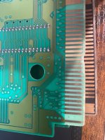
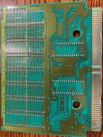
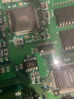
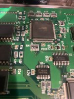
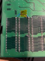
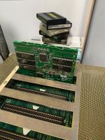
A buddy of mine gave me his Metal Slug MVS cart. He told me it was not working and giving a black screen or the test pattern. I noticed the contacts look like they have been damaged. Potentially from being inserted in correctly?

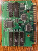
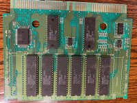
Anyway wanted to get eyes on it to see if it is worth working on.

Appreciate your feedback!
 

Attachments

  • IMG_8999.jpeg
    IMG_8999.jpeg
    398.4 KB · Views: 67
  • IMG_8998.jpeg
    IMG_8998.jpeg
    451.7 KB · Views: 67
While not a great sign for how the cart was treated otherwise, the board makes connection with the contacts further up not down at that edge where the damage is.

If this was the only damage I wouldn't really expect the game to not work before testing.

Clean the contacts, try it and see what you get?
Thanks for the reply! Same as what my friend reported I get the test pattern screen after cleaning contacts which were surprising clean to begin with.
 
Take a pic of each board, front and back and post here. Perhaps there is something that will stand out as to what's wrong.

Also, I'm assuming that they were installed correctly in the cartridge and not reversed, where the top and bottom PCBs were swapped by mistake? Asking only because with that type of damage, it's possible they may have been reversed and then jammed into the slot, causing damage.

Del
Great Qs! I believe they were in the right order. Back end of the cartridge (screw side opposite arrow) the front facing first board had the SNK branding lower right and the second board on the upper right side. Photos attached in that order. Showing the front of the board sand then the respective backs.

Anything you spot I am open to hearing about it. Also happy to do any continuity testing with a multimeter.
 

Attachments

  • IMG_9006.jpeg
    IMG_9006.jpeg
    593.9 KB · Views: 39
  • IMG_9007.jpeg
    IMG_9007.jpeg
    552.5 KB · Views: 39
  • IMG_9008.jpeg
    IMG_9008.jpeg
    599.3 KB · Views: 31
  • IMG_9009.jpeg
    IMG_9009.jpeg
    640.5 KB · Views: 39
Pins 77-79 on that chip labeled IC1 in your first pic appear to be bent & could possibly be shorting next to one another. Are you able to (or are you able to get) someone to try straightening those pins out & seeing if that fixes your issues?
 
Pins 77-79 on that chip labeled IC1 in your first pic appear to be bent & could possibly be shorting next to one another. Are you able to (or are you able to get) someone to try straightening those pins out & seeing if that fixes your issues?
Hi Golden Glover,

Appreciate you spotting that and suggesting I start there. I am game for trying to straighten them out. I am new to troubleshooting boards like this but have done some recapping in the past. For attempting to straighten that section out any suggestions or advice before I get started?
 
I find that very carefully inserting a X-acto knife blade in between the pins you want to straighten & then using the least amount of pressure possible to “straighten” the pins as best as possible (does not need to be perfect, just separated/not shorting one another) has served me well in the past.
 
Will do! I just wanted to make sure we didn’t need to do anything to the docket to straighten the pins. Will report back with pictures. Thanks!
 
Unfortunately no luck. Before I went in I did get a clearer look with my magnifying glass and that section of pin is definitely a mess. I tried to gently create more of a gap but wanted to share a photo under magnification. Test pattern still shows when tested.
 

Attachments

  • IMG_9013.jpeg
    IMG_9013.jpeg
    413.8 KB · Views: 40
  • IMG_9012.jpeg
    IMG_9012.jpeg
    366.1 KB · Views: 41
There are a few spots on the backside of the P-roms that I would be checking continuity on both ends of these spots. I can't tell exactly what's going on but looks like possible damage.

_attachments_img_9007-jpeg.190499_~2.jpg
 
You've tried booting with the two bare boards (plastic shell removed) inserted, right? The PROG board should be in back, with the chips on both boads facing away from you.
 
Agree with all of the above.

Id be checking the pins on that big QFP first, and also the traces on the back
 

Attachments

  • 2.jpg
    2.jpg
    270.4 KB · Views: 17
  • 1.jpg
    1.jpg
    311.9 KB · Views: 17
Hi All,

Thanks for chiming in. I straightened out the pins between 76-79 the best I could and tested the traces on the back. All checked out but one. I bypassed it with 30 AWG cable and retested and get continuity between the points now. Sadly same result though… back to square one.
 
@r27blades Where in NY are you? I'm heading out there tomorrow in the Queens and Long Island area. If you're close enough, I'd be happy to pick it up and try to work on it for you. If not, you can also mail it, I'm in CT.

I wouldn't mind taking a crack at it since I have the tools to do it, including a hot air soldering station to reflow that QFP chip.

LMK.

Del
I don’t think there are enough ways to say thank you! I really appreciate that kind offer and be careful I might need to ask you for assistance in the future. Regarding the Metal Slug X though I might have fixed it?

If I fully reassemble and put it in the case I only get the test pattern but do each board in the slots without the case and I get this.

EDIT: Corrected Link

https://drive.google.com/file/d/1URVBmk7njZs-whxVXX6LPHDe07sP8g9y/view?usp=drivesdk

Looks like it is fully working… but what is the issue with the case? Maybe the case restricts the contact the pins are making?

Photos attached show my soldering for the jumper cable and the boards in slot 1.
 

Attachments

  • IMG_9018.jpeg
    IMG_9018.jpeg
    382.2 KB · Views: 16
  • IMG_9017.jpeg
    IMG_9017.jpeg
    530.7 KB · Views: 17
Last edited:
Works so well it plays as Metal Slug 3? Now I'm confused.
LOL see what happens when you are trying to fix two problem MVS carts? Sorry mixed up the videos. Thanks for catching it - just updated the link in the previous update. Feel free to take a look and let me know if you notice anything off.

If you have any thoughts towards my MS3 audio issue… happy to hear that too lol
 
Just a heads up that I'm getting a Request Access notice for the video now.

As for why it works but not in the shell, after confirming you have it in the boards assembled in the shell the right way (and remember the cart guide is not reversible), then I guess the first thing I would try would be to just put it in another shell if you have one handy.

Other than the obvious refrain of clean the board slots again, clean the cart edge, and finally sometimes I have carts that just need to be backed off a little bit from fully seated to be happiest.

Hopefully you get it working more reliably, but either way, working is nice!
 
Back
Top