What's new

[Looking for Help] Converting NovaBlast to proper Jamma Cab

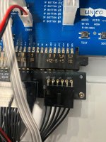
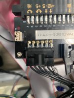
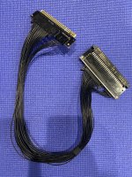
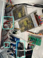
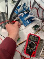
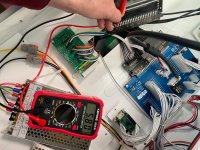
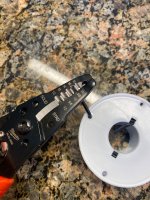
Here is what I got. First photo shows the wiring through the setup: PSU > Unico control board > Jamma harness. I do have some splice connectors in place. Without the MVH6 connected and the system just powered on if I test at the PSU, the Molex mini junior, and both ends of the Jamma harness I receive the same read out of 5.8. Photos also attached. I also snapped a quick photo of the 18 AWG cable exposed thread in my strippers showing them fitting snug for 18 strand.

[EDIT]
My thinking was to get a separate Jamma harness and splice directly out of the PSU to the Jamma edge connecting to the MVH6. My question is without anything attached and no existing drops present would a step like that (while bringing +5V directly to the MVH6) be unnecessary?
 

Attachments

  • IMG_9060.jpeg
    IMG_9060.jpeg
    492.1 KB · Views: 21
  • IMG_9061.jpeg
    IMG_9061.jpeg
    429.5 KB · Views: 20
  • IMG_9062.jpeg
    IMG_9062.jpeg
    501.6 KB · Views: 19
  • IMG_9064.jpeg
    IMG_9064.jpeg
    388.1 KB · Views: 27
Last edited:
Without the MVH6 connected and the system just powered on if I test at the PSU, the Molex mini junior, and both ends of the Jamma harness I receive the same read out of 5.8.

You don't have any load on it. You're basically just measuring continuity.

I see one wire coming out of the PSU for +5V and GND and I see two wires coming out of the Unico IO. That's not enough. You want four wires from the PSU to the jamma edge connector for both +5V and GND.

You can keep using your current setup, but one day when you turn it on you'll notice a burning smell and find charred connectors and wires.
 
@nem
Thanks for the reply. I agree with your points but wanted to clear up how the Molex connector is wired to the Unico board.

I see one wire coming out of the PSU for +5V and GND and I see two wires coming out of the Unico IO.

The Molex connector is actually 4 Ground, 4 +5V, 2 Ground, snd 2 +12V. You can zoom in to see it in the photo.

1747717104291.jpeg


You can keep using your current setup, but one day when you turn it on you'll notice a burning smell and find charred connectors and wires.

Well no one wants that lol so would your suggestion be to not use splicers but pull individual lines from the PSU to the Mini Jr Molex? OR going directly from the PSU to the edge skipping the Unico IO board? OR does the clarification on the Unico board’s power breakdown back that a nonissue?
 
Last edited:
Correct, I would bypass the IO for the power wires to the jamma harness.

What you see at the Molex is actually: 4 Ground, 4 +5V, 2 Ground, and 2 +12V.

Yes, but you only have two +5V and two GND on the output.
 
Yes, but you only have two +5V and two GND on the output.

That would go back to me replacing the Jamma harness, no? I would imagine I would need to ensure x4 for both ground and +5V on the edge and separate x2 for ground and +12V?

I would imagine there are certain shops to go to for them. I have seen Bob Roberts harnesses mentioned in some older threads.
 
Last edited:
I don't see why you would need to replace the jamma harness, buy maybe I don't fully understand. You still haven't posted a picture of the jamma edge connector.

EDIT: nevermind, it's in one of the pics. I would desolder the pins on the edge connector that connect to the PCB and solder the wires from the PSU straight to them.
 
Last edited:
EDIT: nevermind, it's in one of the pics. I would desolder the pins on the edge connector that connect to the PCB and solder the wires from the PSU straight to them.

That's not enough. You want four wires from the PSU to the jamma edge connector for both +5V and GND.

Hi Nem, attached photos of both end of the Jamma harness. As you can see it is [2x] +5V, [2x] Ground, [1x] +12V, and [1x] -5V. It is modified so I don’t see how based on your notes I would be able to tie off 4 lines for +5V and ground. See attached photos.

The edge is modified with a board of sorts for the power side. Seems like replacing it would be easier.
 

Attachments

  • IMG_9066.jpeg
    IMG_9066.jpeg
    394.2 KB · Views: 20
  • IMG_9067.jpeg
    IMG_9067.jpeg
    332.3 KB · Views: 19
  • IMG_9069.jpeg
    IMG_9069.jpeg
    751.2 KB · Views: 16
Last edited:
nova_blast_harness_power_bypass.jpg


Again, I would desolder the power pins from the PCB and solder the wires straight to the pins.
 
nova_blast_harness_power_bypass.jpg


Again, I would desolder the power pins from the PCB and solder the wires straight to the pins.

Hi Nem, appreciate your help but my question is with the board inserted and soldered into the edge connector how would I access the 4 pin locations? Would I need to desolder the whole thing to remove that board and transfer the cables off of the board onto the pins of the edge connector?
 
You heat up the solder pad, lift the pin with a small flat head screwdriver, solder the wire to the pin and put heasthrink tubing over the wire and pin. Rinse and repeat for all eight pins. The pins are thin, they will come off the solders pads very easily.
 
Back
Top