berty
Student
- Joined
- Sep 24, 2016
- Messages
- 27
- Reaction score
- 43
Hi Arcade Projects Team.
I am a collector and restorer based in Australia and I have quite a large collection of arcade and pinball machines that I have restored and documented over the years. One of my machines is Sega's G-Loc Deluxe which I brought as a completely wrecked machine and restored over a number of years.
After years of becoming frustrated with failing and expensive hardware, I endeavoured to build a modern control system for the Sega G-Loc cabinet that replaces all of the Sega hardware, but doesn't hack up the wiring - leaving people with the ability to easily install aftermarket or original hardware.
Latest version: GitHub Repository – Open Motion G-LOC v41
Currently Supported Games
-G-Loc
-Strike Fighter
Current Known Bugs / Issues
v41 is a proof of concept build which you use at your own risk. Emergency stop is currently implemented in code but not working correctly. There are issues with motor polarity detection and implementation outside of the main program loop which needs to be fixed at a later stage.
What is Open Motion G-Loc?
Open Motion G-LOC is a modern, open-source motion control system designed to restore and operate the Sega G-LOC Deluxe arcade cabinet. Open Motion G-LOC is a complete modern replacement for the original Sega 839-0341, 839-0430, 400-5117, and 5117Y motion boards, allowing collectors, arcade owners, and enthusiasts to safely and reliably run their G-LOC Deluxe cabinets again.
Open Motion G-LOC replaces all of the original motion control electronics (which are rare, fragile, and nearly impossible to repair) with a custom-built system based on:
With the right connectors, it plugs directly into the original wiring harness with no need to cut or splice anything. It's debuggable and configurable via an OLED display and serial commands.
It brings G-LOC back to life with authentic seat motion, working Start/Danger lamps, and support for other MAME games. It’s open-source and community-expandable with no proprietary lock-in
Theory of Operation
At the core of the Open Motion G-LOC system is a closed-loop motion control design that emulates the original Sega G-LOC Deluxe cabinet’s two-axis gimbal movement without relying on proprietary Sega hardware. The system is built around an Arduino Mega 2560, which serves as the main controller, interfacing directly with motors, encoders, limit switches, and safety mechanisms. The Arduino receives real-time movement commands over a USB serial connection from a PC running MAME and MAME Hooker, which outputs motion data based on in-game events.
Each axis of motion (left/right and up/down) is powered by a brushed DC motor that moves the seat through a belt-and-gearbox assembly. Rotary encoders mounted on the motor shafts provide precise feedback about the seat’s position. This information is essential for the system’s PID (Proportional-Integral-Derivative) control loop, which constantly compares the current position to the desired position and adjusts motor output to achieve smooth, accurate motion. Unlike the original Sega system which relied on hard-coded responses the PID algorithm allows for dynamic tuning and refined movement behavior.
Safety is partly integrated into the control logic (use at your own risk). Limit switches on each axis act as physical boundaries to prevent overtravel, while an emergency stop circuit, wired as Normally Closed, will instantly disable motion if triggered by boundary sensors or a seat-mounted button. If communication with the PC is lost or motion commands stop, a serial timeout failsafe resets motor targets and recenters the seat to a neutral position, preventing runaway movement.

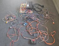
Below are some pictures of the initial prototype that I have made.
Motor Power Supplies and Controllers (MMT-4Q)

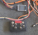
Control Box and LED

Total Setup
.jpg")
A little bit about how this project came about.
My journey began with the noble (but misguided) goal of repairing Sega’s original motion hardware, specifically the 839-0341, 839-0430, 400-5117, and 400-5117Y boards. These power supplies and motion control units are packed with over 200 bespoke components, most of which are long obsolete. (see below).

Like most people who own these cabinets, I have undertake the repairs which are well documented on the French Gamoover forums. These repairs have generally worked and I was able to fix five old Sega boards, however I was finding it more and more difficult to troubleshoot and repair the power supply boards mainly because of inconsistent IC quality and damaged, original PCBs.
At one point, I sought to completely replace the problematic Sega motor supplies by creating my own, new boards that replicated most of the original circuits, but used new, readily available ICs. This led to a prototype which you can see partially assembled in the image below. I eventually abandoned this as it was proving to be very difficult to fault-find and diagnose.

The nail in the coffin for these previous attempts was two-fold. First, both repairing OR replacing the Sega motor power supplies required peope to have a working 839-0341 / 839-0430 board and second, you also needed a working G-Loc main board. Although G-Loc main boards come up from time to time, the 839-0341 board never does. Furthermore and finally, I was finding it way too time consuming to deal with the original Sega Y boards. They are complex and contain many custom chips.
Here is a link to the wiring example.
MAME and MAMEHooker
MAMEHooker (v5.1) bridges emulation and hardware by sending simple, serial commands to the Arduino. Here’s the protocol:
Command Function Example Notes
All commands end in x. Multiple commands can be sent in any order, each with its own x terminator. If a command isn’t sent, the last value stays in effect until updated.
Example command string sent from MAME Hooker:
Q18xR24xS5xT4xA1xB0x
This means:
More information can be found on the main Open Motion G-Loc thread on Aussie Arcade.
https://www.aussiearcade.com/topic/...-loc-motion-platform-project/#comment-1304263
Want to Help?
I am not a coder, nor do I do any of this type of work professionally. This is just something that I set myself as a challenge. That being said, if you would like to help and improve the software or the hardware, I would really appreciate it.
Things that will help the project;
-The project requires MAME to send motor information information to MAMEHooker. If you have knowledge of MAME source, and can add motion commands to games like Top-Speed, Chase HQ, Full Throttle, Afterburner etc, then I can likely make it work on this platform.
-The code is not very good - it works but things like motor direction are still super buggy as of v41. There is plenty of work to be done to make the code better and more robust.
-It is possible to interface Open Motion G-Loc with an original board, using some of the code that @ArcadeMachinist has made. I have only done initial implementation of this as for now, my main focus has remained on MAME implementations.
I am a collector and restorer based in Australia and I have quite a large collection of arcade and pinball machines that I have restored and documented over the years. One of my machines is Sega's G-Loc Deluxe which I brought as a completely wrecked machine and restored over a number of years.
After years of becoming frustrated with failing and expensive hardware, I endeavoured to build a modern control system for the Sega G-Loc cabinet that replaces all of the Sega hardware, but doesn't hack up the wiring - leaving people with the ability to easily install aftermarket or original hardware.
Latest version: GitHub Repository – Open Motion G-LOC v41
Currently Supported Games
-G-Loc
-Strike Fighter
Current Known Bugs / Issues
v41 is a proof of concept build which you use at your own risk. Emergency stop is currently implemented in code but not working correctly. There are issues with motor polarity detection and implementation outside of the main program loop which needs to be fixed at a later stage.
What is Open Motion G-Loc?
Open Motion G-LOC is a modern, open-source motion control system designed to restore and operate the Sega G-LOC Deluxe arcade cabinet. Open Motion G-LOC is a complete modern replacement for the original Sega 839-0341, 839-0430, 400-5117, and 5117Y motion boards, allowing collectors, arcade owners, and enthusiasts to safely and reliably run their G-LOC Deluxe cabinets again.
Open Motion G-LOC replaces all of the original motion control electronics (which are rare, fragile, and nearly impossible to repair) with a custom-built system based on:
- Arduino Mega 2560 as the main controller
- Off-the-shelf DC motor drivers (e.g., MMT-4Q)
- Real-time position feedback via rotary encoders
- Closed-loop PID control for smooth, accurate motion
- Emergency stop and safety logic built into the firmware
- Integration with MAME using MAME Hooker for real-time motion and lighting signals
- A diagnostic OLED screen and test/calibration controls
With the right connectors, it plugs directly into the original wiring harness with no need to cut or splice anything. It's debuggable and configurable via an OLED display and serial commands.
It brings G-LOC back to life with authentic seat motion, working Start/Danger lamps, and support for other MAME games. It’s open-source and community-expandable with no proprietary lock-in
Theory of Operation
At the core of the Open Motion G-LOC system is a closed-loop motion control design that emulates the original Sega G-LOC Deluxe cabinet’s two-axis gimbal movement without relying on proprietary Sega hardware. The system is built around an Arduino Mega 2560, which serves as the main controller, interfacing directly with motors, encoders, limit switches, and safety mechanisms. The Arduino receives real-time movement commands over a USB serial connection from a PC running MAME and MAME Hooker, which outputs motion data based on in-game events.
Each axis of motion (left/right and up/down) is powered by a brushed DC motor that moves the seat through a belt-and-gearbox assembly. Rotary encoders mounted on the motor shafts provide precise feedback about the seat’s position. This information is essential for the system’s PID (Proportional-Integral-Derivative) control loop, which constantly compares the current position to the desired position and adjusts motor output to achieve smooth, accurate motion. Unlike the original Sega system which relied on hard-coded responses the PID algorithm allows for dynamic tuning and refined movement behavior.
Safety is partly integrated into the control logic (use at your own risk). Limit switches on each axis act as physical boundaries to prevent overtravel, while an emergency stop circuit, wired as Normally Closed, will instantly disable motion if triggered by boundary sensors or a seat-mounted button. If communication with the PC is lost or motion commands stop, a serial timeout failsafe resets motor targets and recenters the seat to a neutral position, preventing runaway movement.
Below are some pictures of the initial prototype that I have made.
Motor Power Supplies and Controllers (MMT-4Q)
Control Box and LED
Total Setup
A little bit about how this project came about.
My journey began with the noble (but misguided) goal of repairing Sega’s original motion hardware, specifically the 839-0341, 839-0430, 400-5117, and 400-5117Y boards. These power supplies and motion control units are packed with over 200 bespoke components, most of which are long obsolete. (see below).
Like most people who own these cabinets, I have undertake the repairs which are well documented on the French Gamoover forums. These repairs have generally worked and I was able to fix five old Sega boards, however I was finding it more and more difficult to troubleshoot and repair the power supply boards mainly because of inconsistent IC quality and damaged, original PCBs.
At one point, I sought to completely replace the problematic Sega motor supplies by creating my own, new boards that replicated most of the original circuits, but used new, readily available ICs. This led to a prototype which you can see partially assembled in the image below. I eventually abandoned this as it was proving to be very difficult to fault-find and diagnose.
The nail in the coffin for these previous attempts was two-fold. First, both repairing OR replacing the Sega motor power supplies required peope to have a working 839-0341 / 839-0430 board and second, you also needed a working G-Loc main board. Although G-Loc main boards come up from time to time, the 839-0341 board never does. Furthermore and finally, I was finding it way too time consuming to deal with the original Sega Y boards. They are complex and contain many custom chips.
Here is a link to the wiring example.
MAME and MAMEHooker
MAMEHooker (v5.1) bridges emulation and hardware by sending simple, serial commands to the Arduino. Here’s the protocol:
Command Function Example Notes
- Q##x Set left motor target (pitch) Q18x Position: 1–32
- R##x Set right motor target (roll) R24x Position: 1–32
- S#x Set left motor speed (1–7) S5x 1 = slow, 7 = fast
- T#x Set right motor speed (1–7) T4x 1 = slow, 7 = fast
- A0x/1x Start lamp OFF/ON A1x 1 = ON, 0 = OFF
- B0x/1x Danger lamp OFF/ON B0x 1 = ON, 0 = OFF
All commands end in x. Multiple commands can be sent in any order, each with its own x terminator. If a command isn’t sent, the last value stays in effect until updated.
Example command string sent from MAME Hooker:
Q18xR24xS5xT4xA1xB0x
This means:
- Move left motor to position 18
- Move right motor to position 24
- Set left/right motor speeds to 5 and 4
- Start lamp ON, Danger lamp OFF
- Startup & Initialization
- Loads saved settings from EEPROM
- Sets up pins, sensors, OLED, and waits for input
- If test or settings switches are held, enters those modes for diagnostics or tuning
- Calibration
- On boot, the seat moves between limit switches on both axes to learn its safe travel range
- Maps encoder range to a standard 1–32 scale (matching game outputs)
- Normal Operation (Main Loop)
- Listens for serial commands from MAME Hooker
- Updates motor targets and speeds, as well as lamp states
- Runs a PID feedback loop for each axis to move the seat smoothly and accurately
- Checks all safety inputs—if anything fails, motors stop and seat is re-centered. (Still not working correctly in v41)
- Test Mode
- Allows manual motor movement with buttons
- Displays live feedback from encoders and limit switches
- Toggles lamps for diagnostics
- Settings Mode
- Lets you view and adjust PID/PWM settings and emergency stop logic
- All adjustments are saved and loaded automatically
More information can be found on the main Open Motion G-Loc thread on Aussie Arcade.
https://www.aussiearcade.com/topic/...-loc-motion-platform-project/#comment-1304263
Want to Help?
I am not a coder, nor do I do any of this type of work professionally. This is just something that I set myself as a challenge. That being said, if you would like to help and improve the software or the hardware, I would really appreciate it.
Things that will help the project;
-The project requires MAME to send motor information information to MAMEHooker. If you have knowledge of MAME source, and can add motion commands to games like Top-Speed, Chase HQ, Full Throttle, Afterburner etc, then I can likely make it work on this platform.
-The code is not very good - it works but things like motor direction are still super buggy as of v41. There is plenty of work to be done to make the code better and more robust.
-It is possible to interface Open Motion G-Loc with an original board, using some of the code that @ArcadeMachinist has made. I have only done initial implementation of this as for now, my main focus has remained on MAME implementations.
") , PAR_VOTE_SPACING_US (5), PAR_BUSY_WINDOW_US (200), PAR_POST_DECODE_US (6).
, PAR_VOTE_SPACING_US (5), PAR_BUSY_WINDOW_US (200), PAR_POST_DECODE_US (6).