I know there are various scattered tutorials and videos scattered around the internet regarding this subject. I recently needed to install this switch in my Neo Geo cabinet and I wanted to put every mod in writing while I'm doing this so that anyone can benefit as a single point of reference.
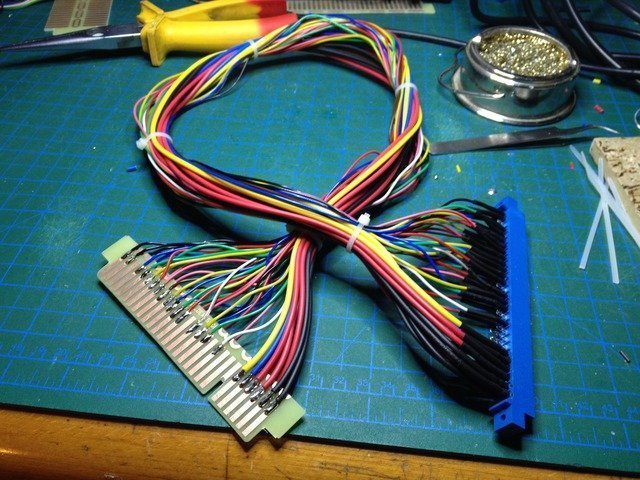
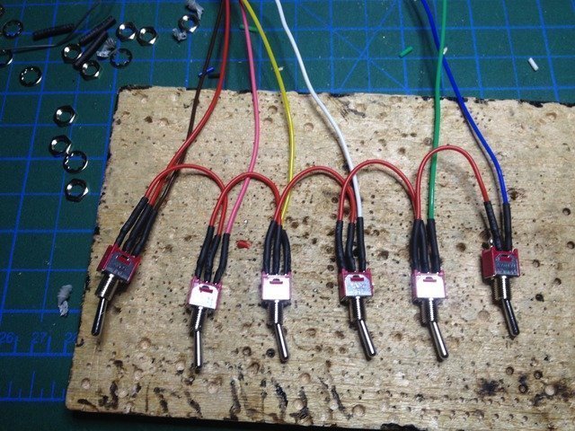
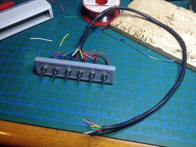
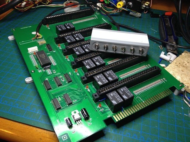
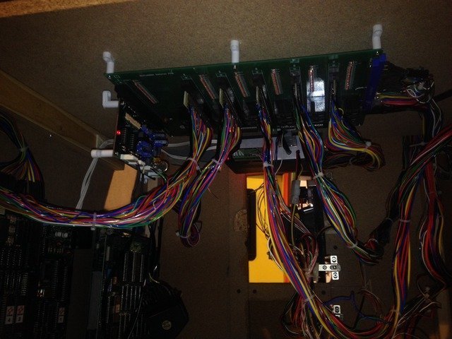
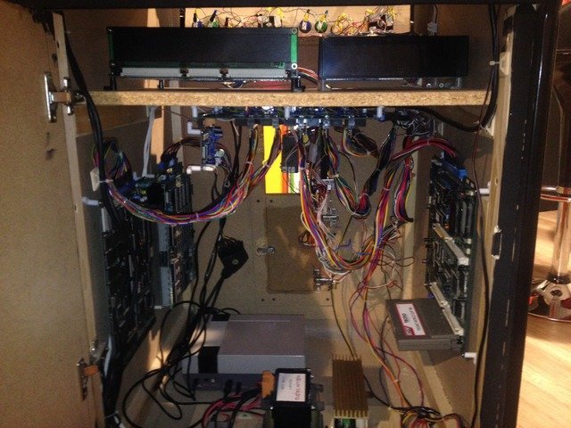
First you have to plan how you'll connect your JAMMA PCBs to this switch. You can either connect them by plugging them directly to the JAMMA sockets on the switch. I find this not so convenient since some PCBs might be too big/heavy that the JAMMA conector cannot support them physically. You either have to physically stabilize these 6 PCBs OR you can use JAMMA extention harnesses. I chose the extension harness option and etched some finger boards and made my own set (they are also sold ready-made on aliexpress)...
Anyway, lets start with the test switch mod...
Not every JAMMA connection is implemented in these Chinese switches. Some of them are not required anyway in a home arcade such as coin meter, slam/tilt switch etc. But from time to time, I DO require a test switch to enter in the test menus of the PCB which is NOT wired by default...
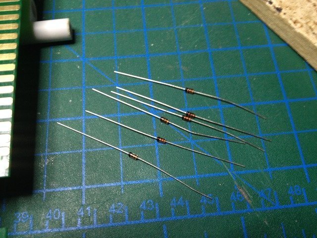
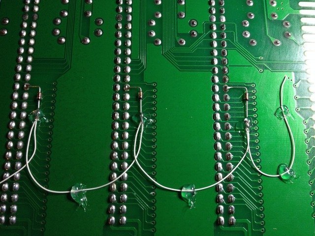
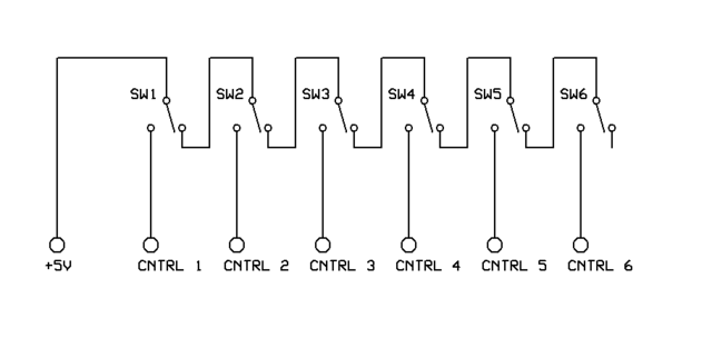
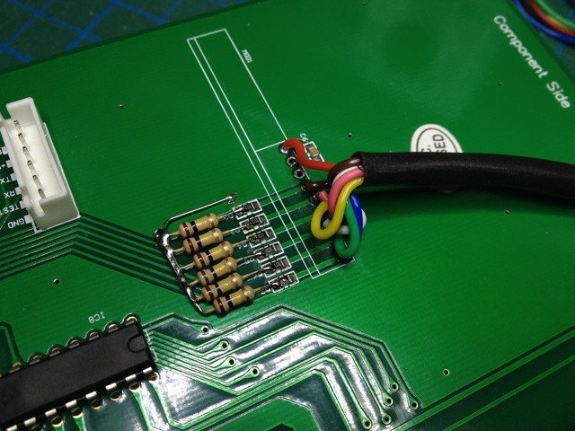
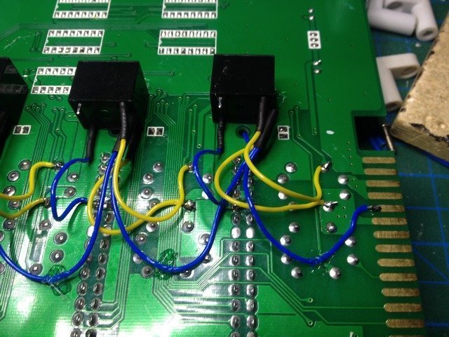
To wire the test switch to all of the 6 JAMMA connectors we have to use some diodes. I used 1N4148 diodes.
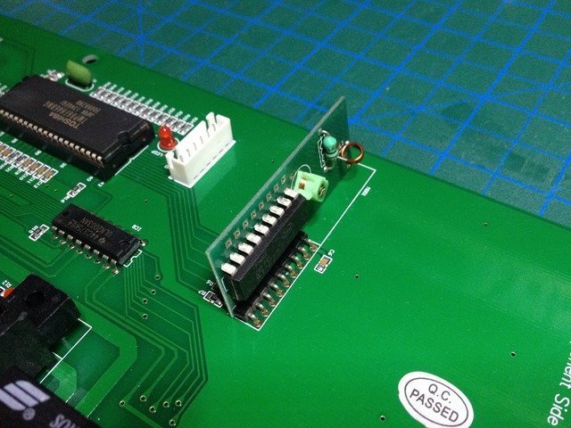
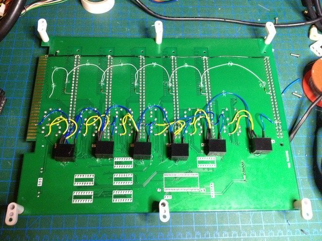
I used 28 AWG isolated kynar wire to pass through a via hole (wire is not touching to the hole) to connect the diodes to "parts side" pin 15 (Test switch pin).
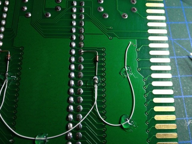
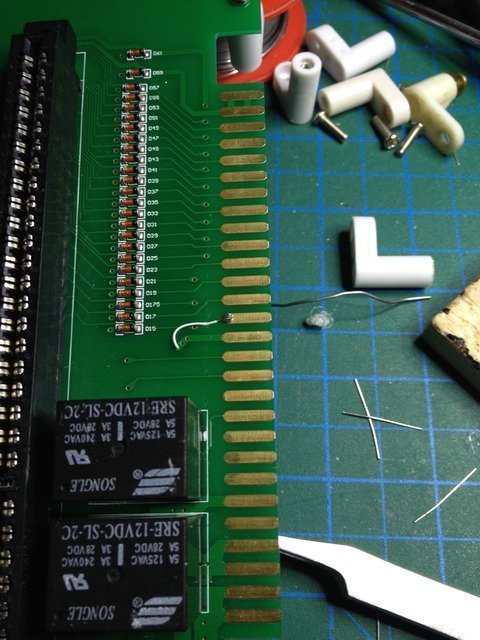
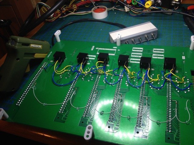
Then daisy-chained the all 6 diodes as in the photo. Notice how diodes are connected because polarity is important. The common wire coming from pin 15 (test switch pin) should be soldered to the cathode (the band marked on the diode) of all diodes. The anodes of each diode should be soldered to the pin 15 of respective JAMMA connector.
First you have to plan how you'll connect your JAMMA PCBs to this switch. You can either connect them by plugging them directly to the JAMMA sockets on the switch. I find this not so convenient since some PCBs might be too big/heavy that the JAMMA conector cannot support them physically. You either have to physically stabilize these 6 PCBs OR you can use JAMMA extention harnesses. I chose the extension harness option and etched some finger boards and made my own set (they are also sold ready-made on aliexpress)...
Anyway, lets start with the test switch mod...
Not every JAMMA connection is implemented in these Chinese switches. Some of them are not required anyway in a home arcade such as coin meter, slam/tilt switch etc. But from time to time, I DO require a test switch to enter in the test menus of the PCB which is NOT wired by default...
To wire the test switch to all of the 6 JAMMA connectors we have to use some diodes. I used 1N4148 diodes.
I used 28 AWG isolated kynar wire to pass through a via hole (wire is not touching to the hole) to connect the diodes to "parts side" pin 15 (Test switch pin).
Then daisy-chained the all 6 diodes as in the photo. Notice how diodes are connected because polarity is important. The common wire coming from pin 15 (test switch pin) should be soldered to the cathode (the band marked on the diode) of all diodes. The anodes of each diode should be soldered to the pin 15 of respective JAMMA connector.
Last edited:
")
")
 I guess we are getting old
