AES 3-6 NEO-B1 pin mapping? (corroded pads)

Kujako

Champion
Joined
Jun 3, 2020
Messages
1,562
Reaction score
990
Location
USA, California
Trying to get any one of my AES systems running, this one had some corroded pads around pin 125 on the NEO-B1.
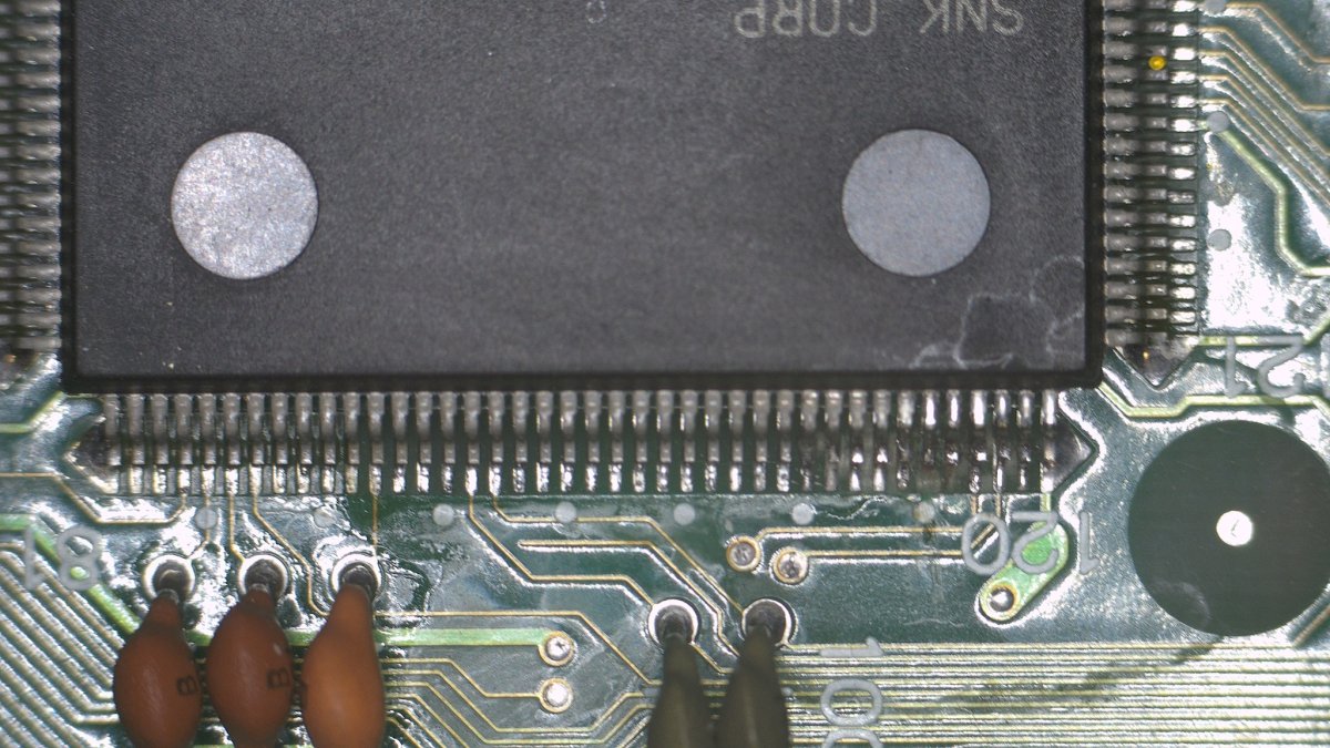
20200101_000302_000001.JPG

Cleaned things up, but I'm not sure where the effected pads run to. Anyone have a decent mapping doc? The old photocopied schematics are a bit hard to read...
 
I have, but that's for the 3-5 not a 3-6. Odds are it's correct for this but would wan't confirmation that there's no significant differences.
gotcha :)

B1 wouldn’t have different pinout so you are pretty safe to try running a wire to another A20 spot and see what happens.
 
  • Like
Reactions: ack
I have, but that's for the 3-5 not a 3-6. Odds are it's correct for this but would wan't confirmation that there's no significant differences.
That part should be the same between 3-3, 3-4, 3-5 and 3-6. The differences between these are mostly the analog audio and video components.
 
Using the provided schematic is great to find the culpit

In this case, the best option is to carefully removing the B1 chip (using low melt solder and airflow) is the best option to rule out corrosion and confirm the continuity issue.

After removal, gently clean the B1 pins with a metal brush, isopropyl, swipe and realign any bent pins before check and putting it back in place.

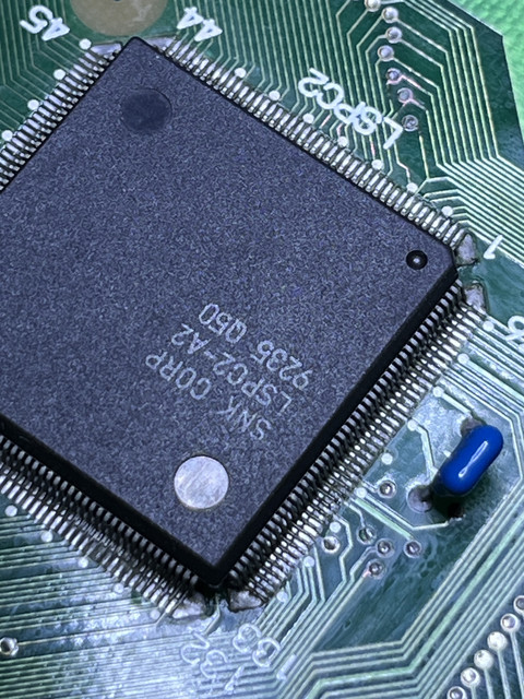
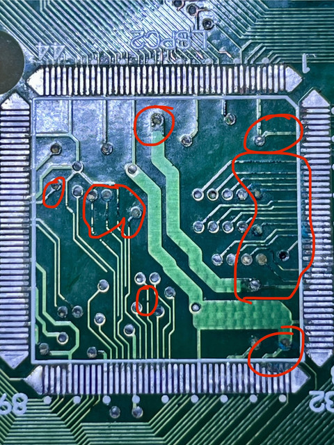
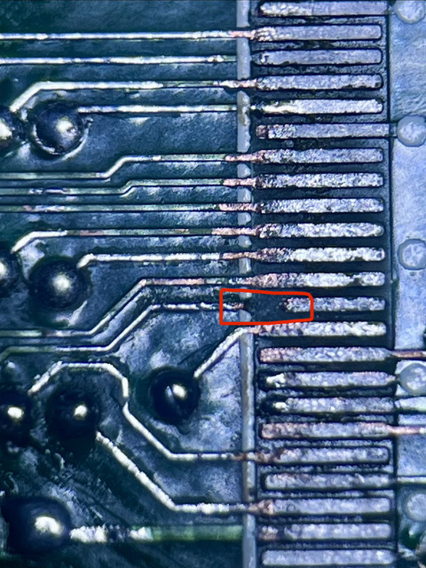
Some example on LSPC2, sometimes the corrosion below is not easily visible..

Before removing (we cannot see the corrosion below..)


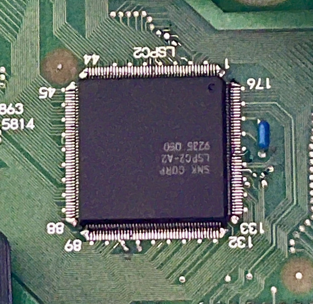
After putting in place :


If you find corrosion here, you very likely have other corroded zones on the board (check the work RAM area as well).

Inspect the case-opening zone of the PCB closely under a microscope.
 
Back
Top