Anyone with Taito Wolf Hardware (Psychicforce 2012)

It's not that complex of a setup, there are 3 boards. the CPU board which is a normal PC mother board. The "main board" which plugs into the CPU board through the graphics card slot; the main board has the JAMMA edge, handles all of the I/O, audio well as Graphics processing. And then the ROM board which sits on top of the main board.

I'm sure if pulled off the ROM board I can identify the Audio circuit, but really all I've wanted out of this thread is to find someone else who owns this PCB to get some basic questions answered.
 
I managed to source an English language manual for this game.

Interestingly this manual removes all references to the DC connector; pretty much ignores it's existence.

also interestingly the audio connector on the main board is clearly stated as being AFTER the amp, it's not a pre-amp out like I thought, which I guess means the amp still could be the culprit on my board, but it also makes me wonder why they even bothered with the connector.

Another fun fact, the last two pages of the manual are a EULA for MS DOS :D apparently this board runs some version of DOS, which is rather interesting since it came out in 1998.
 
It does make a kind of sense in that DOS gave a lot more low level control of PC hardware than Windows 95/98 did, they were really more about making the PC accessible

A lot of games were still released as dual MS-DOS/Windows even around that period... MDK and Dungeon Keeper come to mind
 
Hi! :)
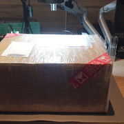
A little package 📦 🇯🇵 arrived yesterday! 🐌🐌🐌🐌😋😊


Capkit : ⚠️ Measured with a caliper; values are approximate.


ECS P5TX-LA Motherboard (Radial Capacitors)

Voltage (V)Capacitance (µF)Diameter (mm)QuantityNotes / Remarks
6.3V470 µF6.5 mm5
6.3V1000 µF8.2 mm6
16V220 µF8.5 mm2
25V10 µF4.2 mm10
25V100 µF6.2 mm2


Taito W Main PCB (Radial Capacitors & SMD Capacitors)

Radial Capacitors :

Voltage (V)Capacitance (µF)Diameter (mm)Length (mm)Pitch on PCB (mm)QuantityNotes / Remarks
6.3V22000 µF18.36 mm42.0 mm14.0 mm1
25V2200 µF16.27 mmNot specified4.1 mm1⚠️Oversized diameter compared to PCB markings. Touches the audio amp casing. Can be easily replaced with a smaller diameter component to better fit the PCB pitch.

SMD Capacitors :

Voltage (V)Capacitance (µF)Diameter (mm)Quantity
16V47 µF6.1 mm1
16V100 µF6.2 mm1


Fan - HF500B50A-12

Main Technical Specifications


SpecificationDetails
BrandSEPA
Exact ModelHF500B50A-12 (MFB50 Series)
Dimensions50 × 50 × 10 mm
Nominal Voltage12V DC
Rated Current0.09A
Fan Speed4,800 RPM
Bearing TypeBall bearing

 
Very nice!

Curious if the audio circuit works with JAMMA power only, or if the external PSU is required.
I thought of you when I was doing my tests last night ;)

The Taito System Wolf brought my New Net City Cabinet's power supply to its knees; even with the +5V cranked up, it kept freezing and crashing.

I used my Easy Arcade 2 with the ANKER PD Power Delivery 60W power supply, and it was absolutely flawless LOL :D

t turns out I just have a dead, cracked optocoupler, so I don't have the "Right" control for Player 1 & 2.
Finding a Toshiba TLP120-4 SMD 16-pin is a real pain in the ass.

I can't find any direct equivalent, let me know if you have any leads for me :love:
 
Very nice!

Curious if the audio circuit works with JAMMA power only, or if the external PSU is required.
Sorry, I forgot to answer your question! ;(

So, the audio comes out in mono directly through the JAMMA edge.
That small potentiometer right next to it isn't for the volume it's actually to switch between Joystick and Rotary functions.

There is also an amplified audio output via a 4-pin Molex 51191-0400 connector, just like on the Taito G-NET or Capcom ZN-1/ZN-2.
I'm going to use my High/Low adapters on that
🐌🐌🐌🐌😋.

Also, to explain how it works: the external DC jack power supply is used only if the cabinet's internal PSU isn't powerful enough.
You absolutely must not use both power supplies at the same time the arcade cabinet's PSU and the external one together,
because it will cause a ground loop effect on the image, and it’s really not safe


I'm going to check and then remove the two bodge wires that Taito made hey soldered two pins together on two EPROMs with a half-melted socket.
Seriously, why didn't they just go underneath the PCB to bridge the socket pins X/ ?
After double-checking that it's safe, I'm going to do the bridge from underneath instead.

If those two EPROMs ever need to be reprogrammed down the road, it'll be a total nightmare to pull them out since they're literally soldered to the socket ?


Last edited:
Back
Top