What's new

CoolFox

Grand Master
Joined
Jul 26, 2015
Messages
551
Reaction score
746
Location
California
I decided to make this since it would be great to have an area where we can share our PCB modifications (either hardware or software). Please no case posts as there's already a place for that. This is strictly PCB modifications, not the exterior. It has to improve something, not just make it look "cool". :P If you added parts to your PCB, please list/give a source for those parts so people don't have to go around wondering where to get them :) If you changed something in the program, please explain what you did and what it improves! I'll start:
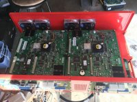
G-Stream G2020
tn_g20.jpg
Added 2 heatsink/fans on the 2 CPLD chips as they get incredibly hot/and used arctic alumina adhesive. I tapped the 5v from the jtags to the CPLDs.

Heatsink/fans: Ebay - Heatsink/Fans

Arctic Alumina Adhesive: Ebay - Arctic Alumina Adhesive

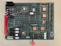
Desoldered the original battery / replaced the SRAM chip with an F-RAM chip. You also have to connect the voltage of the chip to the main line as the SRAM is only connected to the battery.

F-Ram: Utsource - F-Ram

Replace all of the 42 pin 2MB chips on the board with flash chips. Why? Because the board is incredibly heavy with the regular ceramic chips and it cut the weight by about 1/4.

Flash chips: Ebay - Flash Chips
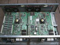

Primal Rage 2

tn_pr2.jpg
Generic Heatsink for CPLD / Arctic Alumina Adhesive. Probably doesn't need it, but I'd rather be safe than sorry.

Arctic Alumina Adhesive: Ebay - Arctic Alumina Adhesive

Heatsink - Bought at local store: Excess Solutions

Switched the regular HDD for a Disk on Module and tapped 5V from the gun ports on the Atari rom board. This board is incredibly picky on which flash HDDs it will accept and I didn't want to have to rely on a mechanical HDD.

EDC 8GB Disk on Module: Bought at local store: Excess Solutions

I will add a few more in the coming days. This is just to begin with.
 
Last edited:
Next on the list:

F355 Challenge Deluxe
tn_bah.jpg

  1. All main boards replaced as the soda leaked on them and destroyed traces (luckily it didn't reach the linking boards)
  2. All batteries and super caps replaced with quality ones.
  3. Secured all of the heatsinks/fans with glue (this is actually what is done religiously on the Hikaru)
  4. Cleaned all of the heatsink/fans
  5. Replaced all fans with San Ace 80L 109L0812H4D01 fans. Old ones in there were basically destroyed. New ones were quite expensive fans, but found them at a overstock place for very cheap. Long life: https://products.sanyodenki.com/en/sanace/dc/long-life-fan/lineup/
  6. The case was really disgusting, had a ton of soda or something spilled on it (common with these games and it had eaten away at the metal). So I had a friend take it to a powder coater and they painted it red.
  7. Cool Ferrari emblem: https://www.ebay.com/itm/3D-Metal-L...321058?hash=item4b645c59a2:g:hpcAAOSwpsFc2iSn
2.jpg


Really pleased how this came out.
 

Attachments

  • tn_bah2.jpg
    tn_bah2.jpg
    149.1 KB · Views: 203
  • 1.jpg
    1.jpg
    159.5 KB · Views: 216
Looks amazing!
 
Reminds me I still need to work on modifying my M2 boards with an FRAM chip vs the battery backed RTC SRAM. I need to learn Eagle so I can design a pcb that will house the FRAM module and resize it to fit into the through holes of the original SRAM chip
 
Gradius IV
2g4.jpg
There is no reason that there shouldn't be heatsinks on the PowerPC chip and the voodoo chips since they get toasty.
  1. Added a Raspberry Pi heatsink/fan to the PPC chip with thermal adhesive.
  2. Added 2x Elina SC050306 heatsink/fans to the 2 voodoo chips. These are flat heatsink/fans and are needed to clear the height requirements.
  3. Removed the old RTC dallas chip, added a socket and replaced it with a Ramtron FM1608 28 pin FRAM chip. Put the chip in blank, let the boot process go and once it's completed, reset.
 
Crusin' Exotica / The Grid
crusin.jpg


Again, Midway using only a crappy heatsink with thermal adhesive that is about as useful as a rock on a GPU chip that gets really hot. Most cabs have a fan inside the cabinet to blow air on this, but honestly I don't trust those.


  1. Removed the shitty heatsink, replaced with a SanAce MC 5v heatsink/fan (same ones on Naomi) and added thermal adhesive. Since the heatsink/fan is a little bigger than the chip, I added some hot glue around it to add a little more support.
 
Capcom CPS3 Motherboard

The PPU gets incredibly warm if it stays on for an extended amount of time.

image0.jpg

  1. Cleaned the PPU, reflowed the PPU, put down some thermal adhesive, placed a heatsink/fan that is a perfect match for it, tapped 5V from the ram...not loud at all...makes me feel better lol.
 
Capcom CPS3 Motherboard

The PPU gets incredibly warm if it stays on for an extended amount of time.
  1. Cleaned the PPU, reflowed the PPU, put down some thermal adhesive, placed a heatsink/fan that is a perfect match for it, tapped 5V from the ram...not loud at all...makes me feel better lol.
Amazeballs!
 
The PPU gets incredibly warm if it stays on for an extended amount of time.
How extended? I've had mine on for two hours now and I wouldn't say it's warm to touch at all.
 
I left it on for about 6 hours or so. I doubt many people will keep it on for this long anymore, but eh...I tend to be too careful lol
 
Hey! I have 2 questions:

1 - What kind of fan and support are you using on the CPS3?
2 - Where on this planet did you get a Primal Rage 2 PCB?
 
@CoolFox What thermal adhesive do you recommend?

Also, i wonder if they sell a heatsink with clip for that footprint/holes.
 
@CoolFox What thermal adhesive do you recommend?

Also, i wonder if they sell a heatsink with clip for that footprint/holes.
I usually don't go after heatsinks with clips because none of the things I put them on have a place to attach it heh.

I recommend arctic silver thermal adhesive.
 
Aorn / Electronic Arts Rabbit

Just a special thanks to Phil for helping me find the last problems and Ekorz for giving me some pinouts. So this is more of a repair/overhaul of the board. I bought the board and it was in terrible condition. It was $50, so I didn't care too much if the main cpu was fried, which they tend to be.

The board looked like this:

preimage.jpgpreimage3.jpgpreimage1.jpgpreimage2.jpg

So it doesn't look too bad via these pictures except for the eeprom. However when I got it, the Imagetek chip had been gone over one more time and they completely fucked up a few traces/many pins weren't even soldered. I had low hopes. Other problems included bad/smashed caps,other reflowed areas that looked like shit, some corrosion on the bottom, sockets completely messed up, broken traces on the bottom of the board and the list goes on.

First things first. The Imagetek chip needed to be fixed. It had to be completely taken off the board, pins straightened and put back on the board. And second the EPM7032 needed to be checked. So I dumped it...luckily it was unlocked. I also put new work ram on as they were giving off questionable signals. Pushing down on the program roms, I saw changes in the behavior of the board, so I pulled them off and looked at the sockets. Disgusting....replaced.

Photo Jan 10, 1 40 33 PM.jpg

I checked the program roms on the board. They either were corrupted or a new dump. Luckily they were a new dump, turned out to be the Japanese version of this game and it didn't seem to be the LOKE test that was already dumped.


After a while I got the board to spring to life. Tons of things were corrupted however and the RAM check only tested the work ram which is quite useless. Also had many errors on the roms. This meant I got to desolder all of the roms and socket them since some of them looked suspect:

Photo Jan 11, 3 16 07 PM.jpgPhoto Jan 11, 3 18 59 PM.jpgPhoto Jan 11, 3 19 32 PM.jpgPhoto Jan 11, 11 11 52 AM.jpg


Everything was desoldered, well on that side anyway. Checking all of the roms...they all seemed OK, so I socketed them all. Tag teaming with Phil, he and I found multiple broken traces that would be really hard to see if these weren't desoldered. We're talking really small broken tracse/inlets.

After that was all fixed. Everything seemed to work! Sound, graphics, inputs, everything!
Photo Jan 19, 4 15 46 PM.jpg
 
Last edited:
Photo Jan 19, 4 15 55 PM.jpg


However it was doing one odd thing. The board would reset right after you lost the first round. I traced it back to the eeprom not having the chip select line attached, fixed it and everything works perfectly!

I cleaned everything, replaced all of the F series logic with Cmos variants of the F series so it's at least runs cooler. Desoldered the old fan header and put a new one on. Attached a 12V SanAce fan with thermal adhesive and glue for support to the Imagetek chip which desperately needed it and I can call this a successful repair/modification. Whew, that one took a while. I'm going to replace the program roms with OTP roms to make the board lighter in the future.

Photo Jan 19, 3 51 58 PM.jpg
 
Last edited:
I noticed Konami put vents on the PCB under a number of chips—the vents can be seen from the solder side. Figured I’d add some passive cooling to my Simpsons board by way of copper heatsinks I had laying around.
 

Attachments

  • BFCC737C-A50D-4ABB-A947-99AEA2124FA2.jpeg
    BFCC737C-A50D-4ABB-A947-99AEA2124FA2.jpeg
    360.4 KB · Views: 123
Back
Top