You are using an out of date browser. It may not display this or other websites correctly.
You should upgrade or use an alternative browser.
You should upgrade or use an alternative browser.
Broken Pins - CPS2 Multikit -solutions ?
- Thread starter redcage
- Start date


wasspat
Student
i've got this issue too (two broken pins).
i've made a bridge with two wire from the two solder (where pins are broken) on the top of the multi to the bottom face of the b-board
if you want I can make a scheme to explain that
i've made a bridge with two wire from the two solder (where pins are broken) on the top of the multi to the bottom face of the b-board
if you want I can make a scheme to explain that
I can send you some pins or you can send the kit to me to repair. Since you accidentally broke them I would just ask for postage.
wasspat
Student
for sure it's the better answer to replace the pins ")
my repair was :
1 - I've broken two pins on the big board
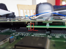
2 - I put two wires (with two color to avoid any confusion) from the top of the solder where pins are broken
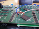
3 - I solder the wires where the pins are connected (just counting the number of solder from left or right)
4 - I put a little piece of insulating tape on the solder (not necessary but it was for my peace of mind)
my repair was :
1 - I've broken two pins on the big board

2 - I put two wires (with two color to avoid any confusion) from the top of the solder where pins are broken

3 - I solder the wires where the pins are connected (just counting the number of solder from left or right)

4 - I put a little piece of insulating tape on the solder (not necessary but it was for my peace of mind)

l_oliveira
Grand Master
At some point I gave Darksoft a design idea which fully eliminate the need of changing any setting for the jumpers, changing the B3 PAL or any pins on the board (after the board is modded that way all pins can be removed and it works with connections from just the two white connectors plus the big board on top of the PRG eproms).
Sadly it was already too late to put it on the board, because the change adds three ICs and the boards are already designed...
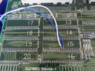
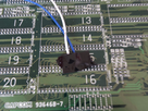
Basically, the GAL/PAL part for the graphics is just a pair of inverters which could be implemented on the kit board. That alone removes all the pins on the graphics ROMs (13-20).
The sound ROMs are 16 bit but the DSP read them in 8bit so a pair of 74LS157 chips near the 11-12 sockets multiplex the 16BIT roms in 8bit. Clonning the multiplexer circuit on the kit board and sending a disable signal through the white connector to the multiplexer circuit on the B board would get rid of the sound pins and also get rid of the need of the extra wire for the sound. Anyone (who has knowledge on electronics) willing to test that idea out just send me a PM and we can discuss.
Sadly it was already too late to put it on the board, because the change adds three ICs and the boards are already designed...
Basically, the GAL/PAL part for the graphics is just a pair of inverters which could be implemented on the kit board. That alone removes all the pins on the graphics ROMs (13-20).
The sound ROMs are 16 bit but the DSP read them in 8bit so a pair of 74LS157 chips near the 11-12 sockets multiplex the 16BIT roms in 8bit. Clonning the multiplexer circuit on the kit board and sending a disable signal through the white connector to the multiplexer circuit on the B board would get rid of the sound pins and also get rid of the need of the extra wire for the sound. Anyone (who has knowledge on electronics) willing to test that idea out just send me a PM and we can discuss.