All three top bidders had high feedback, so I suspect they're legit.And perhaps two of those were seller alt accounts. so all it takes is one sucker.
You are using an out of date browser. It may not display this or other websites correctly.
You should upgrade or use an alternative browser.
You should upgrade or use an alternative browser.
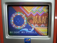
Cannon Dancer/Osman Conversion -> The FREE Edition once and for all (JoeMac/Magical Drop pcb)
- Thread starter TheDeath
- Start date
XtraSmiley
Legendary
Wow! I paid what I thought was a lot for my conversion... I guess COVID job loss hasn't hit obscure arcade collectors!
I like the game a lot, but I think I'm actually leaning toward actual Strider 2 a bit more, even with the stupid polygon graphics!
I like the game a lot, but I think I'm actually leaning toward actual Strider 2 a bit more, even with the stupid polygon graphics!
AlxUnderBase
Enlightened
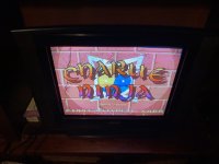
@twistedsymphony sir ive done Charlie Ninja conversion few hours ago since the Chain Reaction pcb had all sockets installed , but i dont hear the vocal samples when you hit the enemies... in rest , image and speed background sounds are present normaly . Where to recheck again to have that vocal samples too ? Thank you for all 
Ps : should i rewrite again 12f & 13h on others 800’s ?
Ps : should i rewrite again 12f & 13h on others 800’s ?
Attachments
Last edited:
verifying the audio EPROMs would be my first step check the speed too.
AlxUnderBase
Enlightened
27c800 are “-100F1” ones , the 4002 one is -12f1verifying the audio EPROMs would be my first step check the speed too.
@twistedsymphony .. sir, the main cpu eeprom has to do something with sample sounds ?
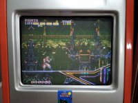
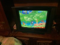
This video is done before speed mod. After the speed mod , all good with that sound tracks
Last edited:
try a 100ns chip replacementthe 4002 one is -12f1
AlxUnderBase
Enlightened
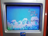
I put a -10f1 and didnt change something ... remain that 800 to rewrite again maybe from there is the problem . I suspect 13h who keeps the okisfx file must be replaced . I powered the board without 12f inserted (oki music file) and is no sound at all with perfect image and movements . Without 13h inserted not perfect image but sounds like before without that samples when you hit enemiestry a 100ns chip replacementthe 4002 one is -12f1
@twistedsymphony sir , I replaced 13h & 12f too on a NOS 27c800 and still no that vocal voices samples
Last edited:
your wire mod looks correct but are you sure you fully cut the trace? have you checked for accidental bridged pins?
AlxUnderBase
Enlightened
I cut only on pin 5 . To be sure i didnt cut other connection i put multimeter to be sure its not nothing lost near and all good siryour wire mod looks correct but are you sure you fully cut the trace? have you checked for accidental bridged pins?
Actually , the traces on the component side are realy solid . On the solder side the cut was much light to cut in comparation with what i did on the componeny side
Last edited:
I don't know what this meansOn the solder side the cut was much light to cut in comparation with what i did on the componeny side
AlxUnderBase
Enlightened
I mean when i cut the trace at pin 5 from was little bit harder than traces from pins 32 from the 13A & 14A socketsI don't know what this meansOn the solder side the cut was much light to cut in comparation with what i did on the componeny side

AlxUnderBase
Enlightened
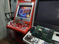
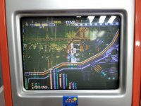
Cannon Dancer is now running on my Data East board
Thank you very much @TheDeath & @twistedsymphony for your awesome lessons!!!
Ps : this is the same hardware where previously tried to put Charlie Ninja, but on Charlie i dont hear the samples sounds when you put credit ,when you are hit and when you hit enemies (okisfx)
Thank you very much @TheDeath & @twistedsymphony for your awesome lessons
!!!Ps : this is the same hardware where previously tried to put Charlie Ninja, but on Charlie i dont hear the samples sounds when you put credit ,when you are hit and when you hit enemies (okisfx)
Last edited:
I've not actually tried a Charlie Ninja Conversion, so I don't have guidance for you, sorry.
playero
Enthusiast
AlxUnderBase
Enlightened
It’s been a while but I think you need to write the eeprom (93c46). If you use the file in mame you need to byteswap it first @playero
And here we go much further : https://shmups.system11.org/viewtopic.php?f=20&t=10566&start=210Thanks!!!
playero
Enthusiast
And here we go much further : https://shmups.system11.org/viewtopic.php?f=20&t=10566&start=210
I think I have something to do to join there.
")
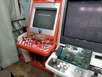
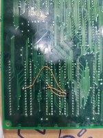
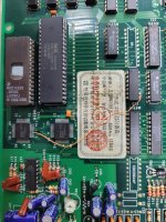
Pictures as I attached, problems left.
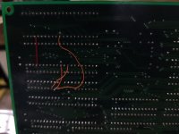
Actually I don't know that I cut the trace right. I cut printed pattern of pcb near 13A, 14A 32 pin.
And wire 11A 9PIN to 13A 14A 32PIN,
11A 8PIN to 13A 30PIN.
Please let me know
Where to cut! And I did right or not.
Thanks!
Attachments
AlxUnderBase
Enlightened
Cut the traces (on the back of pcb - solder side) to Pin 32 on the EEPROM sockets at 13A and 14A, wire these together then Wire them to Pin 9 of the 74LS373 at11AI think I have something to do to join there.
Pictures as I attached, problems left.
Actually I don't know that I cut the trace right. I cut printed pattern of pcb near 13A, 14A 32 pin.
And wire 11A 9PIN to 13A 14A 32PIN,
11A 8PIN to 13A 30PIN.
Please let me know
Where to cut! And I did right or not.
Thanks!
Run another wire from Pin 8 of the 72LS373 at 11A to Pin 30 of the EEPROM at 13A
You are very close sir

ps : solder of you wires seems to be good
Last edited:
playero
Enthusiast
Cut the traces (on the back of pcb - solder side) to Pin 32 on the EEPROM sockets at 13A and 14A, wire these together then Wire them to Pin 9 of the 74LS373 at11A
Run another wire from Pin 8 of the 72LS373 at 11A to Pin 30 of the EEPROM at 13A
You are very close sir
ps : solder of you wires seems to be good
Thanks a lot!
Finally I made it
PS.
When I desolder 13A IC, Maybe I cut a pattern of pcb, so 13A socket didn't work well.
I repaired it, and it works well.