What's new

CPS3 colour issues

JohnnyChaos

Beginner
Joined
Aug 1, 2016
Messages
10
Reaction score
2
Location
East Yorkshire UK
My board is messed up on the RED. It's missing completely on startup and after a while I start to get horizontal red lines showing up where the red should be. It did used to get better eventually, but last time I put it on the red never came back fully.

had anyone seen this and have an idea what might be causing it?
 
please post a pic. That would help others and myself to give you more info about what we thinkg might be wrong.
 
Here are the horizontal red lines. hard to take a pic as they flicker, but you can see them fairly well top left.
once they start, the colour eventually does come back, but more often than not the red isn't there at all.

it came back fully once this past week and looked great, but only for about half an hour or so

20160823_184852_zpseq9cltid.jpg
are you sure it's your board and not the jamma connector or your cabinet or your supergun?
 
yeah definitely.
I've tried it in a couple of Astro cities when I had them
and in both my current jamma'd cabs for fighters

this was the half an hour it was working this week
20160823_202934_zpseasuglar.jpeg


this is how it normally looks.. blue/green only

FB_IMG_1471804940426_zpst3yf0zeh.jpg
 
Last edited:
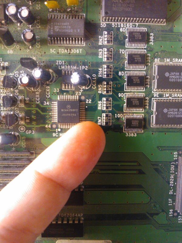
I did try tracing back the red from the jamma edge but struggled to work out where it went.. I always thought this area looked a bit iffy

c7a612c67c5c88796851f072c0c38b41_zpse88e7682.jpg
 
It looks to me like a capacitor problem. Check those right there where you are pointing at.
 
and ccx5 and any other capacitor you see on the board, specially if the top looks bulky.
 
The Motorola IC on the picture with your finger is the DAC (converts digital signals into analog RGB) and you should be able to test if there are signal on it's three output pins.

For that, you can use a standard audio amplifier. Connect the gnd of the amp input to the GND of the game board and then poke the center of the RCA pin with the input on each of the three thick traces to the right of the picture. Each corresponds to one of the colors.

You should hear a noise which varies on what is on the screen, on each of the three traces.
Leo, you should change your Nick to McGiver.
 
thanks a lot I'll have a test. Can I use a logic probe to test them too? I have one I've never opened.

And do you mean the three thick traces coming out the left of the Motorola chip?
 
thanks a lot I'll have a test. Can I use a logic probe to test them too? I have one I've never opened.

And do you mean the three thick traces coming out the left of the Motorola chip?
Yes, those. they go out of the motorola chip, then hit resistors to then reach the inputs of the three transistors which amplify the video signals.

You can probably use the logic probe too but the audio cue is a little better, for video signals as they are very high frequency...
 
Back
Top