

Papapishu
Student
Hi there,
I'm currently working on an OK Baby build, I've gotten quite far in the actual cabinet restoration, but the existing wiring of this cabinet from mainland china left a lot to be desired. The wiring itself was not only disgusting but also confusing.
I'm using Vintage Arcade Gal's instructions for building out a power supply and system board and want to make sure that I correctly wire this isolation transformer in the correct direction. My best guess based on the pictures I (poorly documented) and basic context is that bottom wiring is in, and top wiring is out towards the monitor. But I also know there are weird exceptions so I figured it's best to ask.
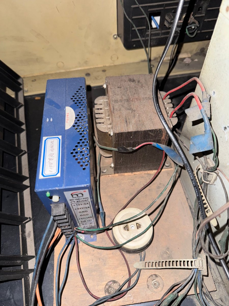
Here's what this thing looked like when I got it (hilariously it seems like they tried to wire it the opposite way and twisted and taped the wires together so green goes to red and red to green).
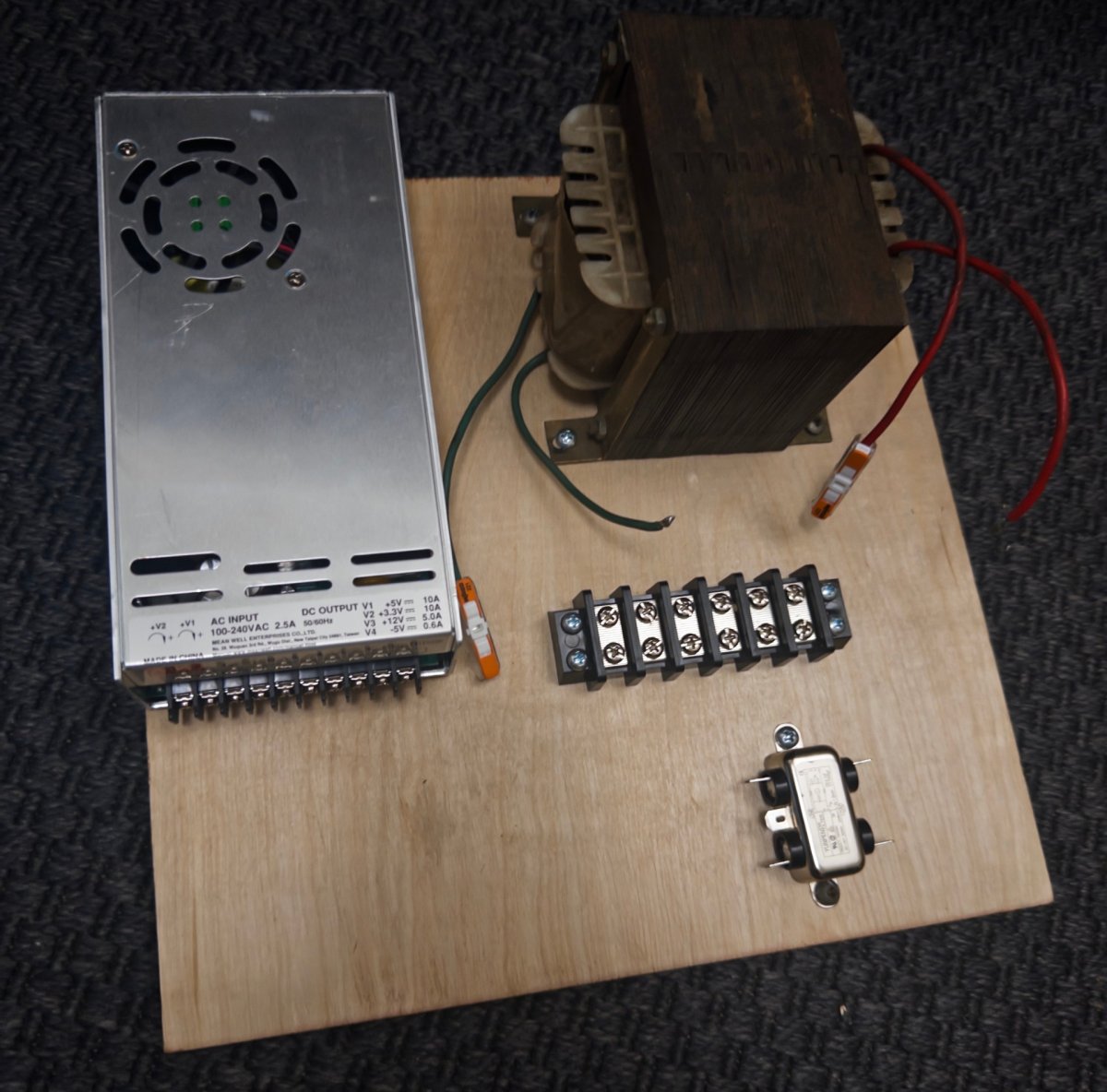
Here's where I'm at currently with the new board (need to properly bracket the psu still)
I'm like 99 percent sure it's Green(bottom) in and Red (top) out based on this but the switched wires gave me pause so I figured it's worth triple checking. Based on the first photograph it also appears that line is right and neutral is left but I wasn't sure if those were arbitrary or not provided they were consistent across the transformer.
Any insight would be great. Cheers.
I'm currently working on an OK Baby build, I've gotten quite far in the actual cabinet restoration, but the existing wiring of this cabinet from mainland china left a lot to be desired. The wiring itself was not only disgusting but also confusing.
I'm using Vintage Arcade Gal's instructions for building out a power supply and system board and want to make sure that I correctly wire this isolation transformer in the correct direction. My best guess based on the pictures I (poorly documented) and basic context is that bottom wiring is in, and top wiring is out towards the monitor. But I also know there are weird exceptions so I figured it's best to ask.
Here's what this thing looked like when I got it (hilariously it seems like they tried to wire it the opposite way and twisted and taped the wires together so green goes to red and red to green).
Here's where I'm at currently with the new board (need to properly bracket the psu still)
I'm like 99 percent sure it's Green(bottom) in and Red (top) out based on this but the switched wires gave me pause so I figured it's worth triple checking. Based on the first photograph it also appears that line is right and neutral is left but I wasn't sure if those were arbitrary or not provided they were consistent across the transformer.
Any insight would be great. Cheers.
