glocknyne
Student
I haven't received it yet so I can't test. I was just wondering if someone that have one knows if it have the same pinouts for the kick harness as the REV B.

based on the real world testing, the results of which are posted earlier in this thread all revisions of this board have the same pinout for the kick harness. That is to say buttons 4 and 5 are only on the jamma edge and button 6 is on the expansion connector.I haven't received it yet so I can't test. I was just wondering if someone that have one knows if it have the same pinouts for the kick harness as the REV B.


@tonyt76 I have the very same issue. I have a Naomi hooked on to a Sega RevB IO, which is hooked to the Blast City I/O. Instead of registering the buttons to 4, 5, 6 it's mapping them to 6, 7, 8 ...I think I figured out the problem. It looks like buttons 4,5,6 on the control panel, register as buttons 6,7,8 on the I/O.And in the NAOMI System test mode (NOT game test mode) you don't see ANY of the button bits changing?


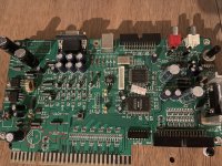
it's a bootleg version of a Capcom IOI need help identifying this type of I/O board.
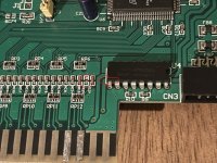
If this going to be used in naomi you can solder the 8 wure oftge molex.direct to the i/o and the two button 3 for 1 player and two player is in the black connector and you have to make a jumper wire to access the 3rd button or assist 1 of one 1p and 2pHi, I need help identifying this type of I/O board. I thought it was a type of Sega Naomi I/O. It's not a Capcom I/O as the CN connectors are not cps2 kick harness connectors. Also, I noticed that it is missing a capacitor and another component seems to be missing to. Is this board busted? I haven't had the chance to try it yet as I don't have the power cable to the Naomi here yet. It should arrive in a week hopefully and then I can try it out. Should I just return this board to the seller?
Yeah it’s going in Naomi. I noticed that there soldering done before on the board for 2 of the jamma edge connectors. So I need a modified connector for it to my cps2 hick harness? Are there official diagrams I can follow on how to connect the buttons?If this going to be used in naomi you can solder the 8 wure oftge molex.direct to the i/o and the two button 3 for 1 player and two player is in the black connector and you have to make a jumper wire to access the 3rd button or assist 1 of one 1p and 2p


Weird, the JAMMA key suggests they're meant to have the components facing down and the solder facing up, no?Anyone have an idea the origin of these two boards, or what they are used for?
Unsure what the ACT-2 PCB is, looks like CPS-1 and CPS-2 kick harnesses connectors on there...
I have no experience or understanding about Model 2 or Model 3, so unsure about that one either, or how it would be used with a Naomi as there's no JVS input on the board.