What's new
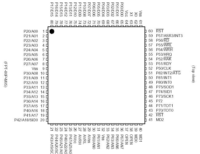
The rom might give a little insight into some of the protocol:

EDIT: These look like error messages per the error codes listed in the manual.

Not sure if these are debug text or protocol code.
E00.E01.E02.E03.E04.E05.E07.E08.E10.E11.E12.E13.E14.E15.C01.C06.
NO ERROR
.. START
.... OVER FLOW ERROR
.... OVER RUN ERROR
.... FRAMING ERROR
.... PARITY ERROR
.... RAM ERROR
.... VOLUME ERROR (HARD)
.... OVER CURRENT ERROR (HARD)
.... VOLUME ERROR
.... OVER SPEED ERROR
.... MOTOR CURRENT ERROR
.... CURRENT SENSOR ERROR
.... POWER ERROR
.... WATCH DOG ERROR
.... POWER ON
.... POWER OFF
....


I'm guessing some of these are debug text.
SPEED = .
AN0_OFSET = .
AN0 = .
AN1 = .
CURRENT = .
PWM = .
MOTOR FORTH = .
HOME_DATA = .
K_DATA = .
D_DATA = .
R_DATA = .
ST_VR = .
HOME_DATZ = .
P66 = .*.*..
64KB CHECK OK.....
RAM CHECK START
... VOLUME,MOTOR CURRENT CHECK START
... I/O CHECK START
... I/O CHECK OK.....
VOLUME READ OK....
CURRENT SENSOR OK....
HARD SAFETY CHECK START ....
ALL CHECK OK .... END ....
VOLUME ERROR (HARD) OK....
OVER CURRENT ERROR (HARD) OK .... . .
 
Last edited:
OK, so DIP 4 seems to be the one set to ON for my WMMT setup, leading me to believe it should be 9600 baudrate out of the Chihiro. I still think the command I'm reading from the Chihiro looks like garbage, though. And so far on the bench, sending random stuff to the FFB doesn't give any kind of response.

I may hook up my 2nd Chihiro to see if I get the same thing from it.
 
Both Chihiros and all 512MB versions of WMMT 1/2 EXPORT and JAPANESE that I netboot seem to issue the same command at startup:
FF FF E8 01 00 00 00 00 00 00

Nothing comes back from the FFB board in response to this. So either all versions I have are incompatible with my board and this command isn't acknowledged, or the board isn't receiving commands.

With all the errors the board seems to be able to generate, I'd expect to see something come back if it thought there were issues with it.
 
Just thinking out loud here.

I may still have some kind of issue with my CMOS/RS-232 converter, but not sure.

The capacitors I re-installed are responsible for the +10V to -10V voltage inverter section of the IC. Given that I measure -10V output, I think I've corrected the issue, however it's possible if either of the caps I installed are polarized, I might have installed in reverse.

At any rate, given that I see the debug message at startup, I can be pretty sure that the CMOS to RS-232 is working.

What I can't verify is that RS-232 to CMOS is working, at least not accurately. I don't have a logic probe/analyzer, so all I can do is measure voltage with my DMM and notice slight swings.

I may try to wire up the IC for a loopback test. RS-232-in to CMOS-out to CMOS-in to RS-232 out. Alternatively this IC has 2 sets of RX/TX and I may be able to reroute communication through the other set if one proves to work and the other doesn't.
 
Last edited:
Also, I've traced the input/output of the converter and see that the CMOS in/out that correspond to the TX/RX being used go straight to the MB90242A.

20094519527601.jpg


If you look at the lower left corner, RX gets converted from RS-232 at the header to CMOS at the converter and the output goes directly to pin 20. TX originates at pin 21 and goes straight to CMOS input on the converter and gets converted to RS-232 at the header.


So what does this mean? RX/TX communication doesn't have much to go through, just a converter and a filter right at the header. If the converter isn't outputting correct CMOS levels, it would be to blame for any RX issues. If it is, then either the MB90242A is bad or something upstream from it, which would be more difficult to track down.
 
I don't have a logic probe/analyzer, so all I can do is measure voltage with my DMM and notice slight swings.
do you have an arduino?http://www.instructables.com/id/Arduino-Oscilloscope-poor-mans-Oscilloscope/
I might be able to get that going on one of the arduinos I've got around. Thanks!

Both CMOS RX and TX idle at 5v. I can confirm with just a DMM that I'm seeing much greater voltage dips on the TX CMOS side when it sends the boot text than I am on RX CMOS coming from the converter when I send random data from my computer. It's not a solid test but makes me suspicious that it's not sinking low enough for the low state.
 
I don't know what else to troubleshoot at this point. The 2nd CMOS TX going into the converter IC was idling at 0v, so that made the corresponding RS-232 output +10v. I fed that into the RS-232 RX from the input I wanted to check and the CMOS RX went to 0v, so I'm pretty sure the converter is working fine and the signals are getting where they need to go, at least initially.
 
so i sniffed out "live" on the maximum tune 3dx cab today.
assume normal dipsw position, only dip4 is on, when power up, nothing happen in serial line, until POWER pin on J101 pin 8, was tight down low by motherboard. It is an input pin. when power pin brought down, the green led will shut off a while, and if all check is ok, the driver emits "E00E00" string. after motherboard (not driver bd) detect this string, it then release the power pin(it back to high state), which then the driver bd will emit "C06C06" string, means power off. and then the motherboard will send hex ff ff ff 01 00 00 00 00 00 00, and driver will answer with 48 01 fe. the answer looks like pot position, but i am not sure. the same hex string sent and answered repeatedly.

if i repeat whole process without HV section of the driver bd connected(110v source and motor connector not connected), after power pin activated(active low), the driver will emit "E10E10" string.

i have confirmed the process by manual sending the command and receive from pc. so the driver need to have the power pin pulled low a while, and then release it, then the host can start sending command and receiving answer.

then i wonder where the debug msg are. it turned out that if we activate dipsw3, and repeat whole process, we will get some nice debug message (if there is an error encountered during check right after power pin activated). But somehow the command hex string doesn't work on debug mode. and yes, activate dipsw1 will show another kind of debug message, like said in copyright msg.

because of repeating send and receive, i cannot really record all of them. when playing the game and steering is activated, i enabled the logging and the command hex sent is like ff ff e4 01 3f 00 3f 00 00 00. then when it's time the steering goes null, i logged again and notice that the 2 byte (two 0x3f as example) are decreasing until 0x00. so i guess it might means steering force for left and right value. still don't know the 0xe4 means.
 
Last edited:
nothing happen in serial line, until POWER pin on J101 pin 8, was tight down low by motherboard
You are awesome! This was the missing link for me!

I now have a board that communicates with the Chihiro just fine. What I don't have is the motor mounted to the steering wheel, so with some difficulty I can fake through the FFB's self test by turning the wheel and then it indicates success and passes the steering test at boot.

I also suspect on the JVS I/O that the POWER pin might be the one for the Start button lamp on OR2SP. This lamp would come on during the wheel test, which I was never able to get through, and never comes on when the steering motor was disabled in the test menu. The question for that is, can it be directly wired to this I/O pin or does it need to go through some gate kind of gate... The pin on the FFB is outputting 5V and needs to sink to ground. I think if the lamp is an indicator of the behavior of the line, it goes high when I would want the pin on the FFB to be high, and off when I would want the pin low. I don't know if the off state would sink it, and not sure what happens if you apply 5v to a pin that's already putting out 5v as its normal state.

So, assuming I don't mess with the POWER pin and manually handle that, I'll need to figure out a way to mount this motor so I can log and figure out this protocol.
 
I also suspect on the JVS I/O that the POWER pin might be the one for the Start button lamp on OR2SP. This lamp would come on during the wheel test, which I was never able to get through, and never comes on when the steering motor was disabled in the test menu. The question for that is, can it be directly wired to this I/O pin or does it need to go through some gate kind of gate... The pin on the FFB is outputting 5V and needs to sink to ground. I think if the lamp is an indicator of the behavior of the line, it goes high when I would want the pin on the FFB to be high, and off when I would want the pin low. I don't know if the off state would sink it, and not sure what happens if you apply 5v to a pin that's already putting out 5v as its normal state.
in my opinion, the power pin is not really related to any lamp output at all. it serves a checking status trigger for the driver board. the pin itself is an active low input. once host trigger and should get answer if status ok or not, then host will put the line back high indefinitely and leave it.
 
in my opinion, the power pin is not really related to any lamp output at all.
Normally, no, but I'm not using Namco I/O in a WMMT cab, so I'm not wired up the for WMMT.

I meant to say in the previous post that I'm on Sega I/O in an OR2SP cab. What is wired stock to the Start button lamp in this cabinet seems to correlate to what the POWER pin should be doing from the Namco I/O. I also confirmed that the FFB pin can be held to ground when the board is powered up, it does its self test and waits an indefinite amount of time for the pin to go high again. Therefore, I believe the lamp I'm seeing does correlate to the this pin. It comes on when the game boots during the wheel test and stays on for the rest of the game. I believe this is the pin that corresponds to the POWER pin on the Namco I/O. Of course it's not a lamp on the Namco I/O, it's what sinks this pin on the FFB.

To further solidify my theory, there is no output test in the test menu for WMMT that lights this lamp, and yet this lamp comes on during wheel test when the FFB board's pin should be high.
sorry if i get you wrong. but the power pin is not on all the time. the power pin get low for a while then get high. and when it's in low state, the driver can not receive any command from host. if that lamp it somehow gets on during wheel test, does it goes off later? if not then you can't use the lamp state to mimic the power pin.
 
Here's the behavior I'm observing in my setup where the motor is just sitting on the ground, not mounted to the wheel and therefore does not alter the wheel pot:

If I power on the FFB board with J101 pin 8 tied to ground, it does a self test where it spins the motor and eventually goes into an error state, likely because of no changes in the wheel pot.

If I move the wheel at all during the time the motor is spinning, the motor stops and the FFB sits in what I assume is a pass state. At this point, I disconnect J101 pin 8 from ground and can boot the game. During the boot, the Chihiro sends the command to check the FFB and the FFB responds and the game continues to boot.

At all times I after this I am leaving J101 high (by not connecting it to ground). While I get no activity in the motor (not sure if due to some error state that the board is not reporting), I do get serial activity both ways. I can manually send the same command from my PC and get a response from the FFB in this state.

Granted that I am not in the ideal setup for testing since I don't know how it behaves when the motor actually alters the pot values, my impression is that J101 pin 8 only has to be low until the game boots, at which point it is always high. Are you saying that's not the case? Is there periodic activity on that pin after boot? What I'm observing in the lamp is that the lamp comes on when I think the pin should be high, but that's only true if the pin is high the entire time after boot.
 
Last edited:
The interesting thing is that I can fake the FFB to the Chihiro now. I can keep spamming the same reply and it never gives an error. This is allowing me to at least see a little bit of the constant stream of commands the game sends out to the board. There are a few places where I can be pretty sure the game wants the wheel centered, such as during car selection. If I leave the wheel centered, I see no activity. If I move slightly left or right, I start seeing commands. I would assume they are the commands indicating that the wheel needs to move back to the center.
 
Oh, just to document this since I don't think it was specifically stated in a previous post, the serial settings for this Namco FFB for Chihiro are:
baudrate: 9600, data bits: 8, parity: none, stop bits: 1

It's incredible what has been discovered so far for this FFB over just the past couple of days. Big thanks to @Dion!

I went from thinking I had a dud to being more confident I've got something that works. :)

My end goal is to figure out the protocol for this board, crack the protocol for the Sega FFB and make a translator so that WMMT can use the Sega FFB. The good news is that the POWER pin for J101 pin 8 on the Namco FFB has no bearing on whether or not the Chihiro accepts a PASS reply and boots.
 
Last edited:
At all times I after this I am leaving J101 high (by not connecting it to ground). While I get no activity in the motor (not sure if due to some error state that the board is not reporting), I do get serial activity both ways. I can manually send the same command from my PC and get a response from the FFB in this state.

Granted that I am not in the ideal setup for testing since I don't know how it behaves when the motor actually alters the pot values, my impression is that J101 pin 8 only has to be low until the game boots, at which point it is always high. Are you saying that's not the case? Is there periodic activity on that pin after boot? What I'm observing in the lamp is that the lamp comes on when I think the pin should be high, but that's only true if the pin is high the entire time after boot.
that's exactly the correct process. you've just explain that you connect it to ground momentarily until it pass the check, then you disconnect them. only after that, the game can send command to driver. i have suggest on previous post you can add small circuit to mimic that.

an example command with wheel force off: ff ff ff 01 00 00 00 00 00 00
an example command when wheel activated : ff ff e4 01 3f 00 3f 00 00 00
still have a lot to digest.
 
you've just explain that you connect it to ground momentarily until it pass the check
Well, not momentarily so much as indefinitely until I can walk to the back of the cab and remove it. :P

I'm not sure if I'll bother trying to rig it up any other way since ultimately I hope I only need it temporarily. Thanks for the info!
 
Is anyone familiar with the Sega servo motors? They're called "servos", but I'm wondering if it's really a stepper motor. Is there a way I can wire this up as a normal DC motor and just have it run when powered? That would be the ideal way to test this Namco FFB, since I wouldn't have to figure out a way to mount the other motor I have which looks like it's going to be a huge hassle.

Edit: Just based on the label of the wiring U,V, and W, I think we're dealing with a 3 phase AC motor, so trying to drive it as a based on the DC power the Namco board is putting out would be difficult. Looks like I get to come up with some custom fancy mounting bracket for my DC motor to fit it in where the Sega motor is.
 
Last edited:
Back
Top