plasticfactory
Champion
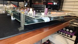
The M92 Multi (everyone should have one!) uses a spacer + PCB foot to act as a standoff stack on the front of the board. This solution is ~1.4mm taller than the rear board stack-up, causing an equivalent amount of flex on the top board.
While I work on a proper enclosure for this, I did a (very) quick model of a printable spacer to remove the flex. The hole offsets were measured with a digital comparator, so location should be very accurate.
The part was designed for M3 heat set inserts, but you could also use a longer bolt + nut.
I included STEP files so that adjustments can be made in the event that other people are using different length standoffs, or any other number of variations that could exist. I think the model as-is will cover most people.
If anyone who needs one does not have access to a 3D printer, post here -- I can probably help.
printables link
Right:

Left:


Here you can see the difference in height + flex (slightly exaggerated as my board had some flex already) when only swapping one bracket:

While I work on a proper enclosure for this, I did a (very) quick model of a printable spacer to remove the flex. The hole offsets were measured with a digital comparator, so location should be very accurate.
The part was designed for M3 heat set inserts, but you could also use a longer bolt + nut.
I included STEP files so that adjustments can be made in the event that other people are using different length standoffs, or any other number of variations that could exist. I think the model as-is will cover most people.
If anyone who needs one does not have access to a 3D printer, post here -- I can probably help.
printables link
Right:
Left:
Here you can see the difference in height + flex (slightly exaggerated as my board had some flex already) when only swapping one bracket:
Last edited:

")