
I leveled up the soldering ability last week. Over the last 6months, I began having a slight vertical collapse issue on my Makvision Tri-sync M3129DB1-72. It was relatively new (to me) but sat in the box most of its life (box date: 6/6/2016) along with a 2nd still in storage.
The first obvious repair is the capacitors as they tend not to do well after sitting for 6-7 years. I wanted to try and minimize the downtime on this, so opted to purchase a cap kit from the guys (AP&R) who sell a cap kit for it. There are several changes on this particular model that I encounter that are not exclusive to the cap kit model variance. A couple of extra caps & one or two missing entirely caps. Shotgunning parts seems generally not recommended but I knew given the time it's sat, I wanted everything possible refreshed and that I likely had anything else on-hand.
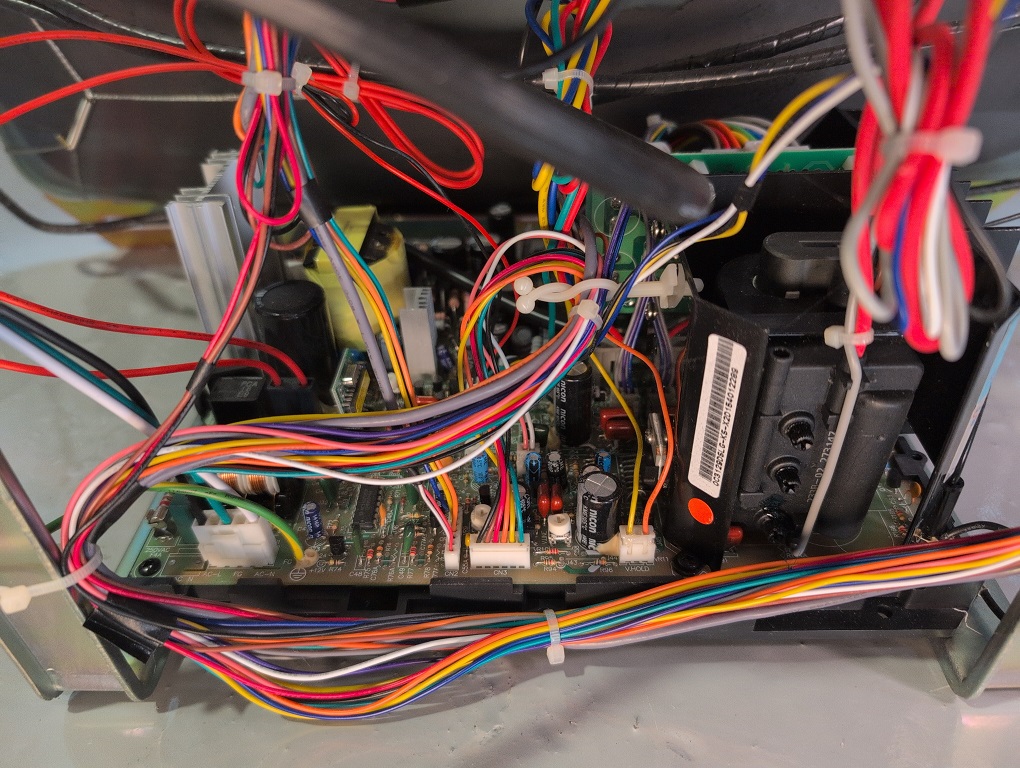
I looked over the board briefly & didn't notice anything screaming at me. I began desoldering all the capacitors - there's a lot, nearly 75. Most came off easily with a couple of stubborn ones and the filter being the most stubborn. Mostly Nicon w/1 or 2 MIEC & other brands. There were two spots of glue on the bottom that first drew my attention when I cut the capacitor free & heard the click of metal. I dug through the glue to find this:
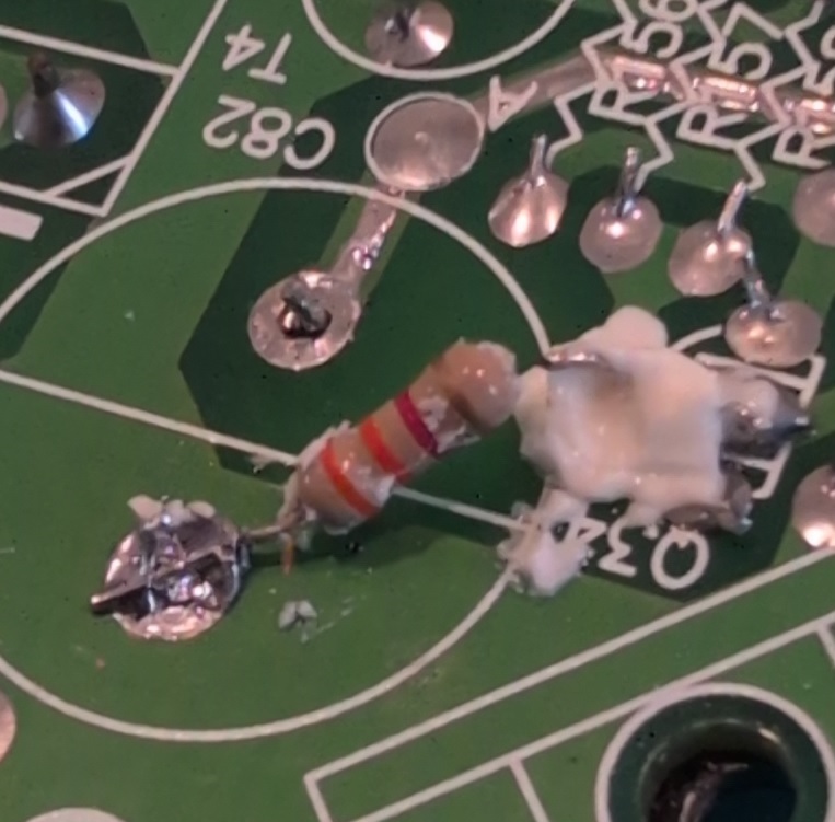
A factory update (or repair?) where they had soldered what looked like a 3.3kohm resistor to the capacitor & jointed it adjacent. I had to revisit this site for a new resistor and re-attach. No idea why this was done as schematics vary between the versions. Fixed pic up below ..
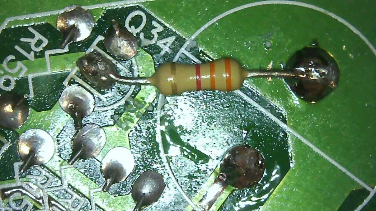
There was a second glue spot on the board and I presumed it would hide similar treasures. I was able to see a jumper wire on the ends and verified where it jumped to before de-soldering the attached cap. I left it as-is, re-soldered it w/the capacitor and the rest was just a lengthy cap list.
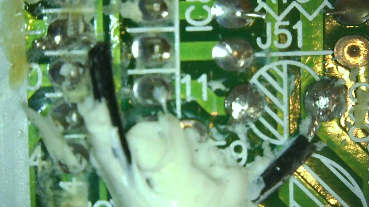
There were notes of replacing capacitor 78A which sat empty on the neckboard. Aside from the upgraded voltages on a lot of capacitors, the only other difference I saw was it using the 400V filter cap vs the more common 200V one.
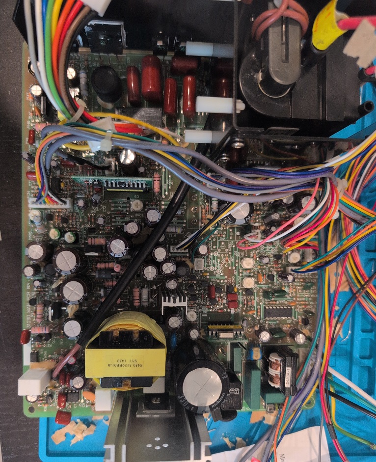
Reattached the chassis & neckboard. Everything powered up OK!
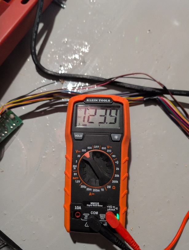
Dialing in the B+. Started up pretty low but remained consistent while adjusting (should be 137V for 31khz. I also switched over to 15k and set it to 72V. I don't have anything for 24K so I assumed it'd be low and left it as-is.
And the payment for time spent...
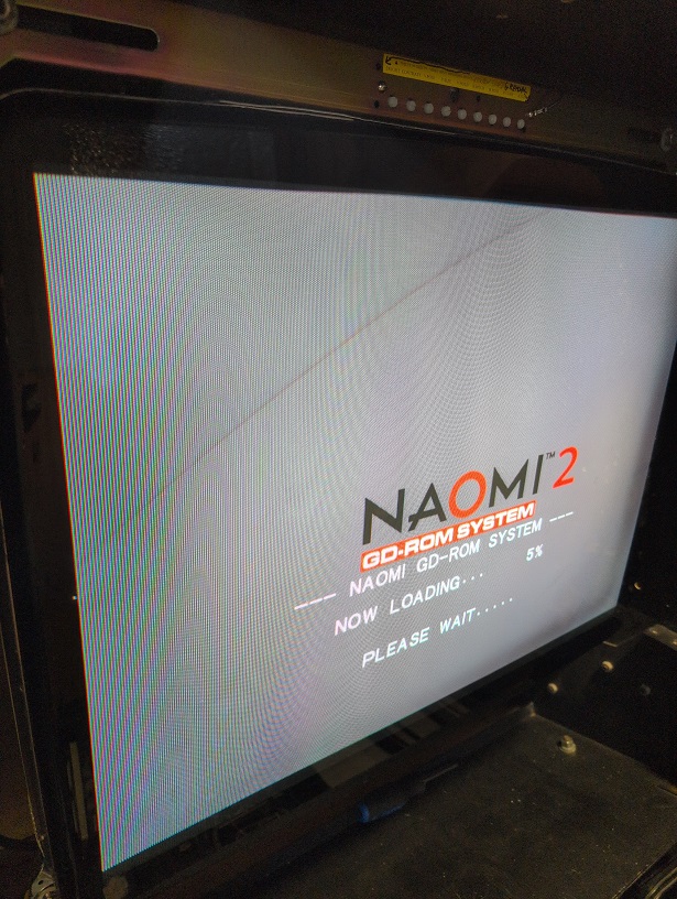
It didn't last however After getting everything dialed in, the jittering vertical issue reappeared shortly after I put the tube back in the cab. I tried switching VGA outputs with a working monitor and the issue remained.
The solder joints on the vertical output IC looked OK but sounds like I'll need to pull it again. Sounds like there's still a couple of things left that it could be -- Vertical Output IC / some reflow guesswork even though the joints look good? Anything else I should keep an eye out for?
The first obvious repair is the capacitors as they tend not to do well after sitting for 6-7 years. I wanted to try and minimize the downtime on this, so opted to purchase a cap kit from the guys (AP&R) who sell a cap kit for it. There are several changes on this particular model that I encounter that are not exclusive to the cap kit model variance. A couple of extra caps & one or two missing entirely caps. Shotgunning parts seems generally not recommended but I knew given the time it's sat, I wanted everything possible refreshed and that I likely had anything else on-hand.
I looked over the board briefly & didn't notice anything screaming at me. I began desoldering all the capacitors - there's a lot, nearly 75. Most came off easily with a couple of stubborn ones and the filter being the most stubborn. Mostly Nicon w/1 or 2 MIEC & other brands. There were two spots of glue on the bottom that first drew my attention when I cut the capacitor free & heard the click of metal. I dug through the glue to find this:
A factory update (or repair?) where they had soldered what looked like a 3.3kohm resistor to the capacitor & jointed it adjacent. I had to revisit this site for a new resistor and re-attach. No idea why this was done as schematics vary between the versions. Fixed pic up below ..
There was a second glue spot on the board and I presumed it would hide similar treasures. I was able to see a jumper wire on the ends and verified where it jumped to before de-soldering the attached cap. I left it as-is, re-soldered it w/the capacitor and the rest was just a lengthy cap list.
There were notes of replacing capacitor 78A which sat empty on the neckboard. Aside from the upgraded voltages on a lot of capacitors, the only other difference I saw was it using the 400V filter cap vs the more common 200V one.
Reattached the chassis & neckboard. Everything powered up OK!
Dialing in the B+. Started up pretty low but remained consistent while adjusting (should be 137V for 31khz. I also switched over to 15k and set it to 72V. I don't have anything for 24K so I assumed it'd be low and left it as-is.
And the payment for time spent...
It didn't last however
After getting everything dialed in, the jittering vertical issue reappeared shortly after I put the tube back in the cab. I tried switching VGA outputs with a working monitor and the issue remained.The solder joints on the vertical output IC looked OK but sounds like I'll need to pull it again. Sounds like there's still a couple of things left that it could be -- Vertical Output IC / some reflow guesswork even though the joints look good? Anything else I should keep an eye out for?
Last edited: