What's new

FS Meanwell PSU Cover Assembly w/ BLUE voltmeter and IEC rocker, custom cables...

For Sale
Ha, no criticism at all, these things are GREAT! Just requests to make them greater!
I welcome it can always do better! Hows this? I moved the wiring around so it goes directly to the side of the PSU that the terminals are on and the switch is located on the far left so the cables will come out the front center. Screenshot 2025-02-19 at 3.50.47 PM.png

Let me know if you think it would work better in a different configuration or you had something else in mind.
 
No, that's perfect!

It keeps all the cables one way when it's sitting in a box or a table!

Now about that knob...
I have tried a few different options for a knob but none really worked well. I would love to hear if you have a suggestion. The main issue is the inability to mount a printed piece of plastic onto the pot. I could print it slightly larger so it slides on top of it but over time it gets loose. You could use something to adhere to the potentiometer but that would leave you with a situation where you would be unable to remove the case if need be (knob would need to be popped off first). Other option is desoldering the pot to install one that has a long handle on it. Again I dont think this is ideal. If anyone has input please feel free to share. :)
 
Here is my cleaned up idea. So basically you print the knob and an attachment separately. This goes on after you get the case on the PSU. You slide the knob in the extra part, then bolt the part down onto the case. The case will have a section that is sticking out and raised (labeled B, not drawn raised because my brain couldn't do it!) that will slide in and hold the knob.

I've never 3D printed or designed, so I'm just shooting in the dark on capability.

So the cover then bolts onto the case, now holding the new knob.

IMG_0597.jpeg

Also section A is notched so the knob can slide in, but on the case, the section labeled B is sticking out to hold the knob and raised (I didn't draw it) so that it slides in and holds the knob on the open side.
IMG_0598.jpeg

Here is a pic of it connected to the case.
IMG_0596.jpeg
 

Attachments

  • IMG_0594.jpeg
    IMG_0594.jpeg
    445.9 KB · Views: 48
  • IMG_0595.jpeg
    IMG_0595.jpeg
    455.8 KB · Views: 45
Last edited:
@XtraSmiley Close to final, everything seems to fit correctly and function as it should. I like how the wires are routed more directly. As an added bonus, you can now easily access the quick connects on the IEC320 socket. This is a nice addition because if the quick disconnects should ever become detached form their respective contact point, you can now reach that area to reconnect them or replace if necessary.
IMG_1872.jpg
Ill be offering this design alongside the original one for people to be able to choose between when ordering.

Still working on the knob for voltage, maybe a few more days and I will have something workable. (Hopefully)
 
Dude, that looks so great I doubt anyone will buy the old design, great work!

Did my knob pictures make sense at all or are they crazy?

I realized I should have edited them to make it more clear, so here is the cleaner, edited pictures.
 
I have had a few people reach out so Im posting to gauge interest on how many parts to buy. Shoot me a DM if you want one and let me know which option you prefer (original or remix), should be ready by this time next week.
 
How goes it on the knob for the remix?
I know this is a late response, but Im almost done engineering it, hope to post the final version later today.

I have also come up with an add-on kit solution to modify the existing versions I have made for people ; essentially allows it to be upgraded with a extension, knob, and snap on cover. Excited to share! :)
 
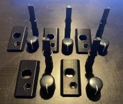
I finally have some "upgrade kits" ready to go! I want to give a huge shoutout to @Fixon for graciously letting me use his pot extension base model to engineer a version that works with my hardware!! :love:
IMG_2061.jpg
Each one comes with the following:
-Potentiometer Extension
-Keyed Knob with Line Indicator
-Custom Snap-In Adapter Plate
-Screw/nut hardware to secure cover (Not pictured, will be black to match rest of cover)

Installation: First, remove the cover from the PSU and disconnect any wires. Now, snap the adapter plate into the hole that provides access to the 5v potentiometer. Then use the supplied screw and nut to hold it in place. Next, slide on the potentiometer extension onto the potentiometer and ensure it covers the entirety of the knob (should be flush with bottom of plastic). Finally, replace the cover by lowering it straight on and vertically, allowing the potentiometer extension to slide through the cover hole. Bolt the cover back onto the PSU with the original screws. Lastly, push the pot knob onto the top of the extension. Your done!

I will take photos of the process, before, after , etc. to post here in a PDF to help people is the verbiage above is too confusing.

If anyone is interested in one please send me a DM!
 
Last edited:
Back
Top